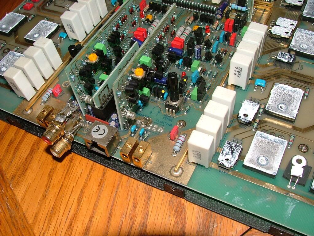
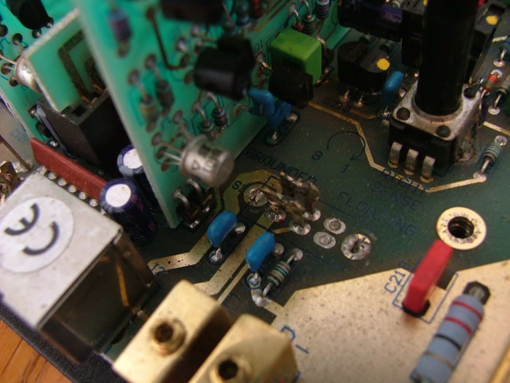
I have new RCAs to install but i need to know what has been removed/ripped from this board .....SW ??? but what kind SPST DPDT ?????
Just a little bit more then I1moreamp wrote:In V2 amps they did away with the switch , in your case the prior owner back one or two steps had decided to jumper the switch in the ground position, which is what PG did when they dropped the switch in V2... so except for coyote ugly its a workable solution.. I heard the switch caused issues with some owners so PG dropped it... and the RCAs would be nice to replace
i also replace the DC offset pot with a ten turn precision type, sort of removes all tediousness of making the adjustment to true zero offset...
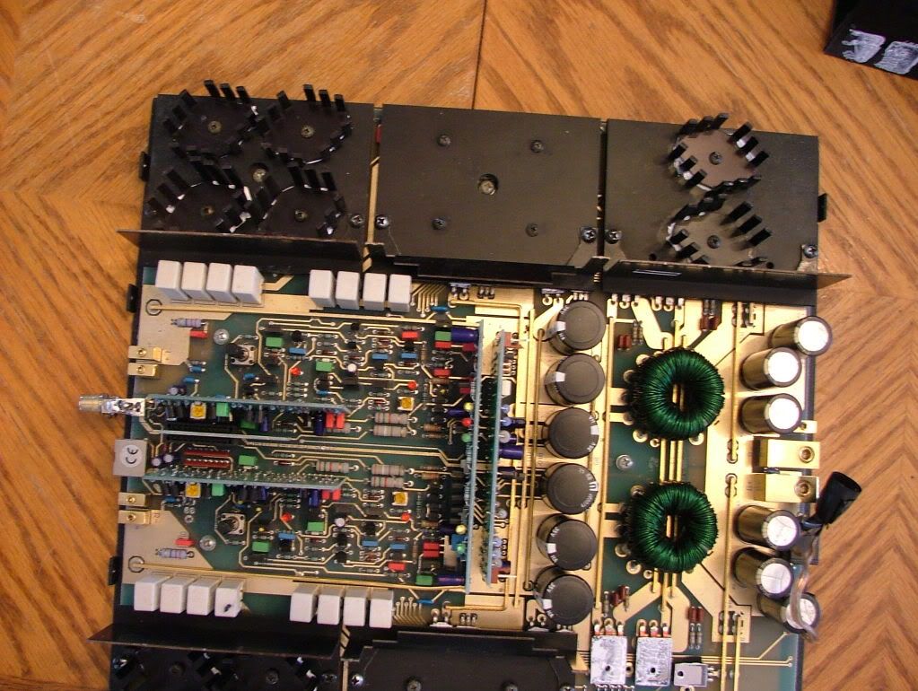
Also check the rear power supply board for bad solder joints on the big drop resistors, PG also did a fix on this issue as I recall, and you want to check it for big brown spots on the circuit board...Maybe post a pic, I know Eric has seen this before also...
Other then these very little things I say pretty nice so far....
Oh and check the two sense diodes on the front card bottom edge to see that they are still intact, if not the amp has been setup to run unlimited . I would put them back if they missing or disconnected..
but what do I know, eh?..