Hi everyone, I'm a proud owner of a MS2125 10th A. ed.
Some days ago the right channel buzzed and died. A friend of mine could repair it if only know exactly the part number of 2 16-pin-chips that are unwritten and completely black.
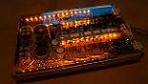
In this pic
[ampguts.realmofexcursion/Phoenix_Gold_MS2125/inside6.jpg]
you can see one of two 16-pin-chips: it's partially covered by the huge white "0" of "10". The other is the simmetrical one (I suppose they're equal).
I really don't know why I see them "written" in some pics in the net... mine are undescribed.
I really thank everyone who could help me finding which chips they are...
I miss my loved amp
Thanks and have a good listening
Yuza
MS2125 10th A. edition. Need chip part number. Thanks :-)
-
yuzathecloud
- Posts: 15
- Joined: Sun Aug 02, 2009 4:19 pm
MS2125 10th A. edition. Need chip part number. Thanks :-)
- Attachments
-
- the amp is not the 10th A. ed. but I underlined the chip position
- Phoenix_gold_ms_2125_foto2.jpg (431.91 KiB) Viewed 5817 times
-
yuzathecloud
- Posts: 15
- Joined: Sun Aug 02, 2009 4:19 pm
-
yuzathecloud
- Posts: 15
- Joined: Sun Aug 02, 2009 4:19 pm
My god... thanks a lot for your speed 
I have only a doubt: I'm seeing now the amp and piece C319 is different, while C325 is positioned -seeing your pic- at the left of the white chip... it could be possible? or maybe it's because they're different models?
Please forgive me... I'm not so a technician...
thanks again my friend
Yuza
I have only a doubt: I'm seeing now the amp and piece C319 is different, while C325 is positioned -seeing your pic- at the left of the white chip... it could be possible? or maybe it's because they're different models?
Please forgive me... I'm not so a technician...
thanks again my friend
Yuza
-
yuzathecloud
- Posts: 15
- Joined: Sun Aug 02, 2009 4:19 pm
-
yuzathecloud
- Posts: 15
- Joined: Sun Aug 02, 2009 4:19 pm
thanks... as I said I notice some small differencies in the schema but I can't realize why...
for exemple in my 2125 I haven't the 8pin chip that in your pic is on the right of the lower of the 2 16 pin chips. Or I haven't the black switch on the extreme right in the center just under the 2 golden long plates...
maybe different schemes for different markets??? I just can't understand... :-O
for exemple in my 2125 I haven't the 8pin chip that in your pic is on the right of the lower of the 2 16 pin chips. Or I haven't the black switch on the extreme right in the center just under the 2 golden long plates...
maybe different schemes for different markets??? I just can't understand... :-O
-
76Trans Am
- Posts: 103
- Joined: Fri Jul 03, 2009 10:32 am
- Location: Wisconsin
-
yuzathecloud
- Posts: 15
- Joined: Sun Aug 02, 2009 4:19 pm

it will be the same chip, it's a pwm chip and very common part so will be cheap too!
Ti1 headunit (unique)
Outlaw in crate.
2x original shrouded ms2250's.
Route 66 in box + custom m100 to match.
Roadster 66 in flight case
Octane LE in box.
Reactor #186 in flight case.
Reactor EQ232
Ti400.2 AL
AX204A + EQ232 + ZPX2 + TBA set
ZCS6 component set
Tantrum+Titanium bass cubes
Ti12d Elite sub
DD5 + DD10 + 6 Ti blocks!
-
yuzathecloud
- Posts: 15
- Joined: Sun Aug 02, 2009 4:19 pm
-
yuzathecloud
- Posts: 15
- Joined: Sun Aug 02, 2009 4:19 pm
Ti1 headunit (unique)
Outlaw in crate.
2x original shrouded ms2250's.
Route 66 in box + custom m100 to match.
Roadster 66 in flight case
Octane LE in box.
Reactor #186 in flight case.
Reactor EQ232
Ti400.2 AL
AX204A + EQ232 + ZPX2 + TBA set
ZCS6 component set
Tantrum+Titanium bass cubes
Ti12d Elite sub
DD5 + DD10 + 6 Ti blocks!
Outlaw in crate.
2x original shrouded ms2250's.
Route 66 in box + custom m100 to match.
Roadster 66 in flight case
Octane LE in box.
Reactor #186 in flight case.
Reactor EQ232
Ti400.2 AL
AX204A + EQ232 + ZPX2 + TBA set
ZCS6 component set
Tantrum+Titanium bass cubes
Ti12d Elite sub
DD5 + DD10 + 6 Ti blocks!
-
yuzathecloud
- Posts: 15
- Joined: Sun Aug 02, 2009 4:19 pm
-
fuzzysnuggleduck

- Soy Milquetoast
- Posts: 4423
- Joined: Wed Dec 06, 2006 1:08 pm
- Location: The best place on earth
- Contact:

no...not to just anyone they didn't as they maintained their on tech and repair guys till recently...however...what they will do now that everything is being outsourced may well be a question worth asking them. Really, is stinger gonna give a fig about 15 year old amp schematic's?...not too sure but it may be worth giving someone over there a buzz...
if the pwm has failed there will most likely be more wrong with the amp...chips don't generally fail without help from other parts not doing their job.....I would go through the entire power supply side and check everything...fets, resistors....diodes....something caused it to tank. I've got a couple amps I've been chasing power supply issues on for months and in one case a year......
not to discourage....good luck....
not to discourage....good luck....
shit...the photos won't transfer over...this is the basics for the sg 3525 which should be very close...check the templates against one another...this may help......
Differences in TLx94 and SG352x ICs:
In general, I have information on the TLx94 ICs. The TL and SG ICs are very similar in function. The main difference is in the comp (compensation) pin function. In the TL ICs, the comp pin must be near ground to produce maximum duty cycle. In the SG, the comp pin must be near 3.5v to produce maximum duty cycle. If you understand basic comparator/op-amp operation and understand how the TLx94 ICs operate, you shouldn't have any problem understanding the SG352x ICs.
Additional Differences between the ICs
TLx94 SG3524 SG3525 SG3526
2 Comparators/Error Amps 1 Comparator/Error Amp 1 Comparator/Error Amp 1 Comparator/Error Amp
No current sense/limit function Has current sense/limit function No current sense/limit function Has current sense/limit function
No on-board soft-start No on-board soft-start Has on-board soft-start Has on-board soft-start
Un-committed output transistors Un-committed output transistors Output Transistors in Emitter Follower Pair Output Transistors in Emitter Follower Pair
No dedicated shutdown pin Shutdown pin must be near 0v for normal operation. Shutdown pin must be near 0v for normal operation. Shutdown pin must well above 0v for normal operation (grounding it shuts the IC's output down).
5v regulator 5.1v regulator 5.1v regulator 5.1v regulator
Deadtime set by voltage on pin 4 (higher voltage = more deadtime) Deadtime determined by resistor between Ct and discharge pins (more resistance = more deadtime) Deadtime determined by resistor between Ct and discharge pins (more resistance = more deadtime) Deadtime determined by resistor between deadtime and ground (more resistance = more deadtime)
Back To The Top
Checking Driver Operation without an Oscilloscope:
This section is to help you troubleshoot power supply drive problems without an oscilloscope. It will help you to understand what your meter is telling you when you check the drive signal that drives the gate drive resistor for the power supply FET. Often, the driver circuit is damaged and will cause the power supply FETs to overheat (and fail, if you're not careful).
The following image shows the basic components of the circuit.
Click HERE to open this in a new window. Maximize the window and/or right-click to zoom in.
This test will not work for MTX amps and amps that use transformers to drive the PS FETs.
This testing can ONLY be done while the power supply FETs are out of the circuit. This testing should be done after removing the blown FETs and BEFORE reinstalling the new FETs. If you've already replaced the FETs and you feel that it takes you too long to remove the FETs to do this sort of test, read section 21 of Tech Tips 6.
Unless otherwise noted, the voltage measurements will be made with the black meter probe on the ground terminal of the amplifier.
With the power supply FETs out of the circuit, the power supply driver IC will (on most amps) go to the maximum duty cycle. This means that you'll read something near 5v DC when you measure the voltage on the gate pad of the board (the pad to which you would solder the gate leg of the FET). If you scroll back up to the voltage on pins 9 and 10 of the TLx94 IC above, you can see that the meter reads 5.34v. That's a common voltage. You'll generally read something between 5 and 6 volts DC.
As a reference, you need to measure the voltage on the drive output pins of the driver IC. For the TLx94, that's going to be pins 9 and 10. For the SG3525, pins 11 and 14 are the outputs. The gate voltage should be within ~1/2 volt of the voltage you read on the output pins of the driver IC. If you read something significantly higher or lower, there is likely a serious problem.
For this test, you'll need a 1000 ohm resistor rated at 1/4 watt or higher. This resistor will be used to attempt to pull the drive voltage up. If the pulldown transistors are working properly, the resistor shouldn't be able to pull the voltage up significantly.
In the circuit below, you can see the two most common drive circuits. The one on the left uses the output of the driver IC to drive the voltage on the power supply FET gate terminal high (towards B+). This circuit is most commonly used with the TLx94 IC. The one on the right uses an NPN transistor to drive the voltage on the power supply FET gate terminal towards B+. The NPN transistor adds to the current drive capability of the drive circuit and is more commonly used in larger (or higher quality) amps. You can find this circuit used with any of the driver ICs.
Click HERE to open this in a new window. Maximize the window and/or right-click to zoom in.
Since this test is mainly used to determine the health of the PNP driver transistor, you don't want anything helping it. In many amps, there are pulldown resistors connected between the emitter of the PNP transistors and chassis ground. For this test, you must desolder one leg of the resistor to remove it from the circuit. You can determine if there is a pulldown resistor by measuring the resistance between the emitter of the PNP drive transistor and chassis ground. If you read something well above 5k ohms, there is no pulldown resistor or the resistor is defective.
Click HERE to open this in a new window. Maximize the window and/or right-click to zoom in.
Below, you can see that the 1k resistor has been 'soldered' into the circuit. One leg is on the emitter of the PNP driver transistor. The other leg will be connected to B+ (soldering it to the center leg of the FET is sufficient). If it's easier, you can solder the PNP-transistor side of the 1k resistor to the PNP-transistor side of the gate drive resistor. Don't solder it to the gate leg side of the gate drive resistor. The gate drive resistor will skew the results. You've probably noticed the damaged pads. This is a junker amp that's being parted-out. With the resistor connected as it is, if the PNP gate drive transistor isn't doing its job, the voltage on the gate will be pulled up significantly above the reference voltage you read on the output pins of the power supply driver IC.
Click HERE to open this in a new window. Maximize the window and/or right-click to zoom in.
Example:
For this test, the voltage was measured on the side of the 1k resistor that was NOT connected to the center leg of the FET. The leg was either not connected, connected to the PNP-transistor side of the gate drive resistor or connected to the gate side of the gate drive resistor. As you can see, the resistor made only a slight difference when connected to the drive side of the gate resistor when the gate drive circuit was in good working order. This is how it should be. For the 'bad' drive circuit, the PNP transistor wasn't pulling down when it should so, when the 1k ohm resistor was pulling up on the circuit, the voltage went up significantly. For reference, the voltage on the output of the driver IC was 5.27v DC.
Bad Driver Good Driver
No 1k Pull-up Resistor 6.4v DC 5.15v DC
With 1k Pull-up Resistor 11.83v DC 5.73v DC
With 1k Pull-up Resistor on Gate Pad 12.01v DC 6.46v DC
I know this may seem like a lot of work but it takes just a few minutes to do the test. You may not feel the need to do it always but if a power supply is giving you grief, you have this test to help you determine if the drive circuit is working properly.
Notes:
The voltages are relative. If the output of the driver IC were 6v, you would want the driver voltage on the 1k resistor to remain below 7v.
-
yuzathecloud
- Posts: 15
- Joined: Sun Aug 02, 2009 4:19 pm
I don't think that is the chip that failed, but my friend has to know which chip is in order to understand the whole circuit, being without schematics.
I already wrote to PG explaining the problem but no answer by now.
bogart, thanks! I sincerely don't understand your explenation not beiing a technician, but I'll send a PM with my mail, so if you have pics or other useful material you can send them without space limits.
Another time, thanks to all!!!!

Repairs for all the non-current PG amps will be done at Rodin in Portland for as long as they want to do them. Not sure about the schematic situation but I'd imagine it will continue as before, not available to the general public. If you have any specific questions try PG support.bogart wrote:no...not to just anyone they didn't as they maintained their on tech and repair guys till recently...however...what they will do now that everything is being outsourced may well be a question worth asking them. Really, is stinger gonna give a fig about 15 year old amp schematic's?...not too sure but it may be worth giving someone over there a buzz...