Have you powered it up without the top cover on? Because the noise may be coming from the transformer but since the amp is covered and the only opening is the sink area you may believe it came from the heat sink area when it may have come from the transformer.
Also when you mentioned you had continuity between the positive and ground power terminals, how long did you leave the test/meter leads on there. Also dont forget to keep an amperage meter on the B+ to monitor how much the amplifier is pulling at idle. If you place a 5amp fuse and it blows/opens it up before you can actually measure the current then you know you have problems (which we already know, lol).
zx350
Re: zx350
Trickyricky, thanks for your patience. I took the chance and hooked it up. It actually nearly made my 10 inch jbl gti pop out of the box, and it also drives my speakers to, so that's all good. BUT the high tone is still there, and then I found out that if I press different places on the print in the right side around the fuse and the heat sink it stops for a while, and then returns...If only you didn't live so far away....Thanks
Jack
Jack
Re: zx350
That was that. Today I tried to power it up and absolutely nothing happened. No light in any of the diodes. I held the wirer with my finger to the battery and it got so hot I couldn't hold it. The fuse didn't blow by the way, and then a pop noise and the smell of burned electronic came. Still no sign of anything burned.
Re: zx350
Are you testing it with the covers removed? What about with the heat sink removed?
Is the fan still connected?
I'd check all transistors for a loose solder or cold solder.
Also, can you post a picture of the repaired trace?
What kind of testing did you do after soldering in the caps? I always use my diode setting to check for continuity between all + sides of the caps and same for the - sides. I also make sure that there's NO continuity between the + and - of any caps.
You then need to move to the power supply. Look up the resistor color chart and see that the gate resistors match their expected values. Then check the FETs. One should be connected to +, another connected to -, and the middle leg should be connected to its gate resistor. You can use the diode setting to check that those have the correct continuity.
A few of these and a few of those.
Creator of www.phoenixgoldregistry.com
hit me up to add your limited edition amps.
Creator of www.phoenixgoldregistry.com
hit me up to add your limited edition amps.
Re: zx350
Ok, by further inspection I found this!!!! I have tried to do what you suggested, but when I use my meter on the positive and negative terminals I beeps like crazy without stops...I also didn't repair the traces, just made 2 jumpers on the backside of the print....
Jack
Jack
- Attachments
-
-
Re: zx350
So you have a short somewhere. That MOSFET is for sure blown...it could be causing the short or it could be caused by the short. Remove it and then check the continuity between + and -. My first thought is that if a short caused it to blow then it would would be blackened. That almost looks like the heat sink was over tightened.
Also, can you take a picture of the repaired trace? I ask this because even a small piece touching another trace could cause a major issue.
Also, can you take a picture of the repaired trace? I ask this because even a small piece touching another trace could cause a major issue.
A few of these and a few of those.
Creator of www.phoenixgoldregistry.com
hit me up to add your limited edition amps.
Creator of www.phoenixgoldregistry.com
hit me up to add your limited edition amps.
-
trickyricky
- Posts: 1653
- Joined: Sun May 06, 2012 8:01 am
Re: zx350
Thats because there is more than one faulty fet. Either way it goes you have to replace ALL of them not just the one that failed. Another thing to keep in mind is that those fets have gate resistors and are "fuse" type so if they fail/open they will not show signs of distress so you'll have to ohm them out. These are 33ohm fuse type resistors (orange orange black brown black), also remember that diode I mentioned that was between B+ and ground...that may also be bad (you'll have to check it, I remove one side and that way you can accurately test it out of the circuit without totally removing it....but thats your call).
If your worried about installing new fets and blowing them up then install just one for each side (you see how you have 3 for each side?). Also the power supply's IC may have taken a beating as well, so it's a good idea to replace it (unless you want to try installing one fet per side than see how that goes).
If your worried about installing new fets and blowing them up then install just one for each side (you see how you have 3 for each side?). Also the power supply's IC may have taken a beating as well, so it's a good idea to replace it (unless you want to try installing one fet per side than see how that goes).
Re: zx350
I have now ohm'ed the gate resistors, here is the result. The diode between + and - I don't where is. Is it possible to pinpoint on the photo what to change?? I'm no electronics expert but I will not give up.. All your help is absolutely amazing...Thanks
Jack
Jack
- Attachments
-
-
Re: zx350
All 6 of those resistors should measure the same. I would start by removing all of the FETs. Try power it up. Use your multimeter to measure the voltage at that right leg (voltage going through the gate resistor). You should get about 7 volts AC and 7 volts DC. If you get all AC or all DC, then you need a new PWM. If you do get about that then you can proceed with 6 new gate resistors and 6 new fets.
Silly question, you made sure that you installed the caps you reinstalled the new ones in the same orientation as the originals, right? It looks right from the picture but you can never be too sure.
Silly question, you made sure that you installed the caps you reinstalled the new ones in the same orientation as the originals, right? It looks right from the picture but you can never be too sure.
A few of these and a few of those.
Creator of www.phoenixgoldregistry.com
hit me up to add your limited edition amps.
Creator of www.phoenixgoldregistry.com
hit me up to add your limited edition amps.
Re: zx350
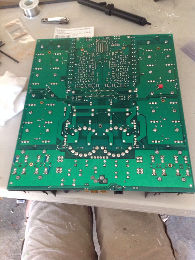
I removed all the FETs, and now I have a beeb from the meter for only short time 2 sec. I also removed the resistors and 2 of them are for sure dead. Are there also vias in all holes for fets and so on? these rings are coming of the print.
- Attachments
-
Re: zx350
If you use the ohmmeter across the b+ and b- you should see a value, but it should not be steady, it will continue to go up, that's because your capacitors have a charge in them. As you have a short across them (the meter itself) the caps should discharge. If you have a steady ohm load then there's some other sort of problem (possible that diode that Ricky is talking about is damaged).
If there's no steady ohm load then try powering it up and doing the test that I said to do. I've been in your shoes before, it's very frustrating.
Edit: looking back at your last picture, I think you removed more than you should have. It looking like the power supply fets were in groups of 3, but you removed 8 components plus 6 resistors...check that those components are all the same. 2 of them might be something else...
The damage that you are speaking of is because of too much heat or leaving your iron there too long. Make sure you are using the right size iron tip and if you are not using a station with an adjustable temp control then be mindful of how long you leave the iron in one place.
It can all be fixed later by adding jumpers where conductivity is not found. Here's one example of my work to correct this... (Look in the bottom left of the board
A few of these and a few of those.
Creator of www.phoenixgoldregistry.com
hit me up to add your limited edition amps.
Creator of www.phoenixgoldregistry.com
hit me up to add your limited edition amps.
Re: zx350
The parts I need (sf163 diode) and (ndp7060 transistor) can't be bought I Denmark....sf163 I can't find anywhere and the ndp's I found is from China.........This is turning in to a thriller, and maybe I have to retire this project.
-
trickyricky
- Posts: 1653
- Joined: Sun May 06, 2012 8:01 am
Re: zx350
jvj wrote:The parts I need (sf163 diode) and (ndp7060 transistor) can't be bought I Denmark....sf163 I can't find anywhere and the ndp's I found is from China.........This is turning in to a thriller, and maybe I have to retire this project.
The SF163 is obsolete so you will have to sub it with either a FEP16CT or MUR1615CTG (I would go with the FEP16CT).
Mouser has the NDP7060 for 3.24 a piece, or you can sub these as well with either IRF3205 or IRFZ46-48 (I would go with IRF3205). Isn't there a mouser distribution center in Europe?
Re: zx350
you can use your diode (conductivity) mode on your multimeter. a diode is like a 1 way check valve...it should have conductivity in one direction but not in the other. If bad they can short out, but more often they blow into an open state.
A few of these and a few of those.
Creator of www.phoenixgoldregistry.com
hit me up to add your limited edition amps.
Creator of www.phoenixgoldregistry.com
hit me up to add your limited edition amps.
-
trickyricky
- Posts: 1653
- Joined: Sun May 06, 2012 8:01 am
Re: zx350
Just don't forget the 5amp inline fuse.jvj wrote:Ok, there all good. Looking forward to getting the new parts and see what it does...it will be nerve wrecking to power it up once I'm done...
-
trickyricky
- Posts: 1653
- Joined: Sun May 06, 2012 8:01 am
Re: zx350
Those are correct value. Try this for fun, get one of those 33ohm resistors you took off (the original) and place 12v across it. Of course you'll have to use proper safety procedures such as: safety goggles or face shield, gloves, switches to turn circuit on and off.
You'll see that the originals will just open internally, will not show any major damage....now the ones you bought try the same experiment and you'll see something different (unless they are fuse type, only datasheet specifies) they might have flame proof enamel but they will act very different from the originals when they fail.
DON'T DO THIS if your not 100% certain of what your doing, if I was to attempt this experiment I would use a switch to apply power to the resistor and I would be at a good safe distance and make sure I have a fire extinguisher at hand just as a safety precaution.
Now if you only ordered the exact amount of resistors then DO NOT ATTEMPT the experiment
You'll see that the originals will just open internally, will not show any major damage....now the ones you bought try the same experiment and you'll see something different (unless they are fuse type, only datasheet specifies) they might have flame proof enamel but they will act very different from the originals when they fail.
DON'T DO THIS if your not 100% certain of what your doing, if I was to attempt this experiment I would use a switch to apply power to the resistor and I would be at a good safe distance and make sure I have a fire extinguisher at hand just as a safety precaution.
Now if you only ordered the exact amount of resistors then
-
trickyricky
- Posts: 1653
- Joined: Sun May 06, 2012 8:01 am
Re: zx350
jvj wrote:Will they be dangerous to put in then?
I dont know their characteristics so I can't tell you. As far as I know they could be fuse-type therefore no need for testing, but again I dont have the datasheet nor do I have one to do such experiment. I just stick with fuse-type because as you can tell THEY CAUSE NO DAMAGE when they fail, hard to even tell which on failed/open.
Even if they are not fuse type you can install them, if they do fail when the power supply fails they might just leave a little residue behind but doesn't cause the board to melt down unless they are some weird cheap resistors.
Go ahead and use them just leave a little space between it and the board.
-
zeropoint0.5
- Posts: 593
- Joined: Fri May 13, 2011 12:03 am
Re: zx350
http://dk.farnell.com/international-rec ... atch=rel_3
here is a good alternative for the NDP7960 fets.... use them with also 33 ohm gate resistors.....
the resistors you ordered with just 4 colorbands are 5% resistors, with 5 colorbands you have 1% resistors...
if they are 33 ohm you are fine....
I remember one time i replaced a powersupply in a zx350 with 6 irfZ48 and 330 ohm resistors , and that was
not a succes at all.....................
the 4 big diodes at the input are 5401 types....
you can all find this easily on farnell/mouser/digikey......
if i order in Belgium something from mouser, it has to come from Memphis , USA, and it takes just 2 days
before i receive it......