Bass Cube Remotes


And taking the time and effort to build them.
SSAudio.com ~ Dcon / Icon / Xcon / Zcon ~
Caraudio-forum.com
HomeAudioForum.net
PG Stash: Xenon 1200.1 & 200.4, Bass Cube, RCA's
Caraudio-forum.com
HomeAudioForum.net
PG Stash: Xenon 1200.1 & 200.4, Bass Cube, RCA's
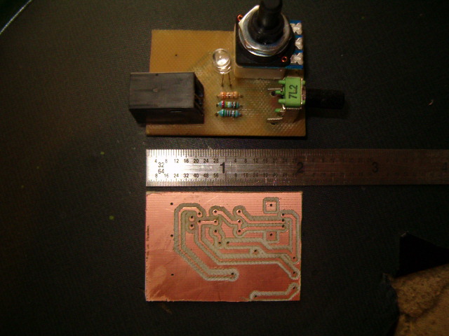
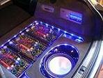
Well, preliminary results are in. Prototype remote is working fine. I ended up doing it single sided as there are only three traces on the top of the board and it is easier to solder jumpers than to setup and mill the top side and have it line up with the bottom.
The pros:
It works exactly like the factory remote.
I don't think it looks too bad.
I think I made the sumbitch smaller, it measures 2x1.25, could make it smaller yet if I wanted to kill myslef and make them with smd parts...
The Cons:
I ordered the wrong RJ-11 plugs, I got the damned flavor that is for a telephone handset cord, it takes a narrower modular plug, and there is no such cable with the correct end on either end unless you make it yourself. I of course ordered 12 of the SOBs, but I will get the right ones. Anyhow, I filled a standard phone cord down and the screwdriver is in the pics to hold it in place.
I am not real thrilled with the switch pot. It is evidently only available in the vertical variety from my sources. It was not specified, and I was hoping for horizontal. I found a web site selling what appears to be a similar style of pot to the original, but no data sheet for it, and I cannot setup the PCB w/o the dimensions, I don't really want to order a bunch from an unknown source, but I will go that route if you guys dont like option "b".
Option "B" I can use two of the less expensive non switched pots, and a small push button switch. The board will have to be a tiny bit wider to put all of the controls in the same plane. Another option would be to get vertical frequency pots and keep on with the original switched pot. I kind of like this as it make a tidy mountable package, and the LED can be soldered directly to the board like I have it.
Okay, here are the pics. The milling went well. Took a few trial boards to get it done, but the end result is nice.
Tell me what you want my to do for final layout. Majority rules here, so if you don't like what we come up with, I don't have a problem with you backing out.
Later,
Jason

That is awesome!
Perhaps a solution to your POT issue would be a basscube remote remote... IIRC the LPL pot was the same as the one on the basscube, so you could instead hook up another RJ11 output, plug in an LPL, and use that as your boost control. Then you can leave the freq control module hidden somewhere, since that is much less likely to be changed (or put a second output if you're really nuts )
)
Perhaps a solution to your POT issue would be a basscube remote remote... IIRC the LPL pot was the same as the one on the basscube, so you could instead hook up another RJ11 output, plug in an LPL, and use that as your boost control. Then you can leave the freq control module hidden somewhere, since that is much less likely to be changed (or put a second output if you're really nuts
It may be the same value, but it isn't the same pot. I have one here, and it has no switch built in. You would not believe how difficult it is to find a pot with a switch that is independent of pot position, i.e., there are a lot that have a switch at the start of the pots travel, like an old school volume knob, but that wont work for this, as most people want to be able to shut it off with out having to readjust.
On an interesting side not, I found a potentiometer IC that allows push button control of the resistance, I may build one based on that just for shits and giggles.
Later,
Jason
On an interesting side not, I found a potentiometer IC that allows push button control of the resistance, I may build one based on that just for shits and giggles.
Later,
Jason
Something like this? It is a mini push on/off SPST switch. With something like this I could likely keep the board the same size, as the small 10K pots have a lot smaller footprint than the switch pot. I can mount these horizontal or vertical. Another option would be a small illuminated toggle, lights up for on, and eliminates the separate LED.

Later,
Jason
Later,
Jason
No problem at all guys, we are just lucky my wife and kids went out of town for a few days, otherwise I may not have had time to get going on it... Getting married and having kids sucks all of the time right out of your day  Wouldn't trade it for anything though...
I am going to try to PM everyone on the list tonight and tell them to get their butts to the thread and vote. I will make another order the next day, whatever we decide. I did already place the order for the correct RJ11 jacks, had to order enough for a digikey minimum order, so I threw them in.
There is a slim chance I may be able to find the original pots. I will research more tonight. I don't think that our newest member has posted up yet, but PG-Scott emailed me the original BOM with the manufacturers part numbers for the problem parts I have. If and when he does introduce himself, make sure you thank him as well!
Later,
Jason
looking good jason, i would be happy with what ever you go with, shame the original pots can't be picked up from somewhere though!
mark.
mark.
Ti1 headunit (unique)
Outlaw in crate.
2x original shrouded ms2250's.
Route 66 in box + custom m100 to match.
Roadster 66 in flight case
Octane LE in box.
Reactor #186 in flight case.
Reactor EQ232
Ti400.2 AL
AX204A + EQ232 + ZPX2 + TBA set
ZCS6 component set
Tantrum+Titanium bass cubes
Ti12d Elite sub
DD5 + DD10 + 6 Ti blocks!
This is very cool to be able to follow your work. As for voting, I am in for which ever is easiest for you to build because you are doing this for us. 
SSAudio.com ~ Dcon / Icon / Xcon / Zcon ~
Caraudio-forum.com
HomeAudioForum.net
PG Stash: Xenon 1200.1 & 200.4, Bass Cube, RCA's
Caraudio-forum.com
HomeAudioForum.net
PG Stash: Xenon 1200.1 & 200.4, Bass Cube, RCA's
Quick update, I ordered seperate switches, and more pots and the right modular plugs to put all of these together. I have to redesign the cad work for the board to fit the changes, and I can't tell you for sure when I will have them done, as time is still in short supply for me, but the rest of the parts should be here this week, and I will try to get them turned around and out to you guys.
Later,
Jason
Later,
Jason
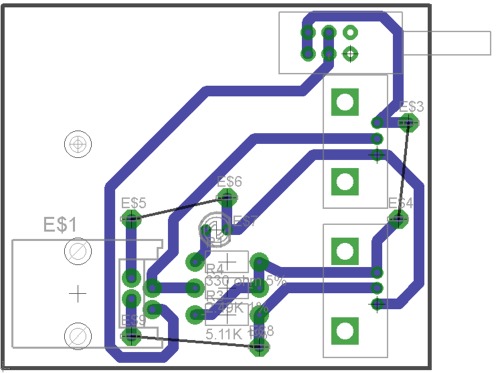
I finished the CAD work for revision 2. I ordered more pots, the correct modular jacks, and push button switches. The pushbutton switches are identical to most of the ones used in PG amps. I ordered round button caps for them too (you will see when I get one done). The new board dimensions are 1.75" x 2", so about .5" wider than the first one. It is still going to be tiny. I also added solder pads to allow for jumpers on the top of the board to eliminate the three top side traces, and not have to do point to point wiring on the bottom of the board. I generated the numerical code for the mill already. I am working for the next four nights, but with any luck, if SWMBO doesn't have a lot of crap planned for me, I will get a few turned out on my next days off.
Here is a pic of the new board layout:
Later,
Jason
Here is a pic of the new board layout:
Later,
Jason
great stuff jason, coming on a treat 
Ti1 headunit (unique)
Outlaw in crate.
2x original shrouded ms2250's.
Route 66 in box + custom m100 to match.
Roadster 66 in flight case
Octane LE in box.
Reactor #186 in flight case.
Reactor EQ232
Ti400.2 AL
AX204A + EQ232 + ZPX2 + TBA set
ZCS6 component set
Tantrum+Titanium bass cubes
Ti12d Elite sub
DD5 + DD10 + 6 Ti blocks!
Outlaw in crate.
2x original shrouded ms2250's.
Route 66 in box + custom m100 to match.
Roadster 66 in flight case
Octane LE in box.
Reactor #186 in flight case.
Reactor EQ232
Ti400.2 AL
AX204A + EQ232 + ZPX2 + TBA set
ZCS6 component set
Tantrum+Titanium bass cubes
Ti12d Elite sub
DD5 + DD10 + 6 Ti blocks!
Yeah, if you can hook me up with about a month of free time with no wife and kids and household projects, I am pretty sure that I could have this project licked, as well as about 350 other things I am working on...
Seriously, my only problem is lack of time. You would think it would be easy to set up the mill and just let it go, but I find myself standing there babysitting it, drool running out the corner of my mouth, and wondering what else I can make it do. It is frigging addictive. I don't know how a CNC can possibly save a job shop money! I am sure it will eventually get boring, but the fact of the matter is, you kind of have to keep an eye on it to be sure nothing goes haywire, or tooling breaks and it sits there cutting air.
I am just glad you all are being patient with me. I hope to be able to offer you guys a cnc cut mounting bracket/housing as well, but I am not sure if I will have time or not.
Later,
Jason
No rush. Take your time. You are using your time to make these for us, so I can wait.
SSAudio.com ~ Dcon / Icon / Xcon / Zcon ~
Caraudio-forum.com
HomeAudioForum.net
PG Stash: Xenon 1200.1 & 200.4, Bass Cube, RCA's
Caraudio-forum.com
HomeAudioForum.net
PG Stash: Xenon 1200.1 & 200.4, Bass Cube, RCA's
-
mhyde71

- Dr. Jekyll
- Posts: 6231
- Joined: Sun Jan 20, 2008 8:34 pm
- Location: PG FanBoy in Green Mtn Vermont
- Contact:
here here!denim wrote:No rush. Take your time. You are using your time to make these for us, so I can wait.
JLUK when/where/& how much for money to send.. no rush, I have gone this long with no remote.. but certainly would like to give it a shot/try one out... keep up good work Mate!
M
PAST WORK/S HERE::
https://www.facebook.com/KhameleonKoatings/photos_albums
https://www.facebook.com/KhameleonKoatings/photos_albums