Page 1 of 2
A little ZX600Ti mod...
Posted: Tue Aug 19, 2008 12:49 pm
by Jacampb2
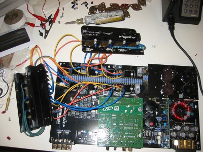
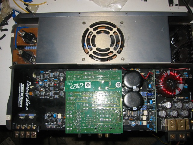
Here is a little peak at what I was up to on my one day off. This has been running on the bench all day at low to moderate volume with no thermal issues, and no fan... Many thanks to C who put this bug in my ear in the first place

The plan is to make new isolation plates out of solid copper. If they can all be common to one buss which is also the HS, then that simplifies things a bit. In the pictures they are mounted with mica insulators on some old t0-3 HS's I had. I know it isn't a good idea to run the amp for long periods of time with the bias transistors not thermally tracking the output transistors, but I had to see if these would work

Feel free to give me any input
BTW, it sounds really good, better than the tantrum 600.4 I have been using to run the basement computer sound system.
And the picture...
Later,
Jason
Posted: Tue Aug 19, 2008 12:54 pm
by Bfowler
*subscribed*
Posted: Tue Aug 19, 2008 1:02 pm
by stipud
You are a mad scientist by profession, aren't you?
Show me your doomsday device.
itm
Posted: Tue Aug 19, 2008 2:22 pm
by kg1961
WTF that great more info let me know how it goes!!!!
Posted: Tue Aug 19, 2008 2:29 pm
by Zarnov
Whoa....

That's F'n cool!!
Posted: Tue Aug 19, 2008 3:57 pm
by Jacampb2
You know stipud, I have gotten the mad scientist tag before, as well as McGyver, and a few others... You should see some of my other craziness. This one isn't that bad

It is funny you should mention the doomsday device though, I am always a little worried my neighbors are going to spot me sitting in a metal folding chair in my underwear
soldering at 2am and call the cops...
There is not really a whole lot more to tell. I am using the Zx600 for a test bed, because it has some other issues I am sorting out, and if it burned to the ground, I wasn't much further behind where I started
The plan is to do this to all of my 800.1's after I get this one together and run my sub for a while. The reason behind TO-3 devices is simply a matter of power handeling and dissipation. Each of the original transistors were 150w devices, and each of the TO-3's are 250w devices. All other things equal, the TO-3's can handle much more current than the flat pak devices can. If I force the power supply to remain in high voltage mode regardless of load impedance (similar to the ZPA mod out there, but not as simple), then the amp will make a lot more power into lower impedance loads, and be in no danger of burning itself up.
It would be very simple to just drill the stock isolation plates for TO-3 mounting, but I want to go copper for a few reasons. One, I have a bit of .25x4 copper in my scrap bin that would make good isolation plates, and cost me nothing but time. Two, copper has excellent thermal conductivity. Three, I can solder tubing to copper plates for liquid cooling (more on that later). Four, and most importantly, it will look sweet as all fuck.
As for the liquid cooling, I bought three of my 800.1's from Tristan with no case, as well as a 900.7 from Maxxxsq with no case. I plan to build one big amp, all in one chassis with 4 800.1's and 1 900.7 and need a way to cool it well in tight quarters.
The biggest downfall of this all of this is simply the cost. The TO-3 transistors are a lot more money than the originals. The ones I am using retail for about $4.5 each, and I will need at least 40 of them to complete the 800.1's. I will probably end up using an extra pair per channel on the 800.1's as well, and that pushes me up to ~50 or so, more if I am going to actually sort through them all and beta match the pairs, which should be done.
Later,
Jason
Posted: Tue Aug 19, 2008 4:16 pm
by stipud
So I assume you are keeping the stock powersupply transistors then? Or do you have other plans for them?
Posted: Tue Aug 19, 2008 4:37 pm
by Jacampb2
Well, they are rated at 60a each, and IIRC, there are six per rail. Finding higher rated PS fets will be easy if the need arises, but I think, at least for the zx600, that the stock ones will be fine.
Later,
Jason
Posted: Tue Aug 19, 2008 7:46 pm
by stipud
Leaving a fan to cool them then?
Posted: Tue Aug 19, 2008 9:46 pm
by Jacampb2
Yes, I didn't make it entirely clear, but when I put the ZX600 back together, it is going to be fan cooled only. The only reason I am not going to drill the 600's isolation plates for TO-3 mounting is so that I don't butch up something that someone can use. I will either get little aluminum mini sinks for the TO-3 outputs (they look virtually identical to what PG put on the isolation plates, but the transistor sits inside it) or I will try my hand at making some little "hat" type heat sinks out of copper tube to fit the top of the TO-3's.
The only evidence of this mod from the outside of the stock amp case should be the shine of copper and the transistor hats through the exhaust grills.
Later,
Jason
Posted: Tue Aug 19, 2008 10:01 pm
by Jacampb2
Oh yeah, the 800.1's will get liquid cooling for both the PS FETs and the output BJTs.
For the Zx600, I will make a copper isolation plate for the PS FETs as well, but it will serve no different purpose than the original, I will just do it so it matches.
There is one small issue I did not mention about the copper plates. The aluminum isolation plates are anodized which insulates them from the BJT's collectors and the FET's drains. There are no insulators between the devices and the plates. It was done to increase thermal efficiency, and is one of the reasons that the mini sink amps are capable of their power levels and small(ish) footprints. I believe the plates are seperated (one plate for the NPN transistors, one for the PNP and one for the FET's) is so that if the anodization were to develop a problem and the plates became live, that they wouldn't destroy the works.
With the copper plates, anodization is not a possibility, and I do not want to use insulators and compromise the thermal efficiency, so the plates are going to be at rail potential for the BJTs and at 12V for the FETs. In and of itself, this is not a problem, but if something drops through the grill and shorts it could be catastrophic. Also, it makes the amps a fair bit more dangerous to work on, and if the case were to contact the plates, well-- you might have your doomsday device after all
Later,
Jason
Posted: Tue Aug 19, 2008 10:50 pm
by KHPower
That sounds amazing! You should be designing amps for someone or some company
Posted: Tue Aug 19, 2008 11:25 pm
by Jacampb2
KHPower wrote:That sounds amazing! You should be designing amps for someone or some company
LMAO, thanks, but no. I have no idea what I am doing. I am learning, but I am teaching myself as I go. It is strictly for fun and to give myself a sense of accomplishment. I firmly believe that you either have to study this shit for a long damn time, or just be some kind of "specially touched" person who just gets it. Everything I have endeavored to learn about electronics has been a constant struggle. I pick a lot of stuff up easily, but this has almost driven me to go to school... I am starting to come around the curve though, thanks to many excellent books.
Later,
J
Posted: Wed Aug 20, 2008 12:01 am
by Wakeup
nice work !!! Keep us informed!
Posted: Wed Aug 20, 2008 4:23 pm
by Jacampb2
Thanks! I brought the original isolation plates with me to work tonight. If time permits I am going to scan them w/ a scale in the picture, and start the cad work for the copper plates.
Wish me luck!
Later,
Jason
Posted: Wed Aug 20, 2008 6:57 pm
by KHPower
Jacampb2 wrote:KHPower wrote:That sounds amazing! You should be designing amps for someone or some company
LMAO, thanks, but no. I have no idea what I am doing. I am learning, but I am teaching myself as I go. It is strictly for fun and to give myself a sense of accomplishment. I firmly believe that you either have to study this shit for a long damn time, or just be some kind of "specially touched" person who just gets it. Everything I have endeavored to learn about electronics has been a constant struggle. I pick a lot of stuff up easily, but this has almost driven me to go to school... I am starting to come around the curve though, thanks to many excellent books.
Later,
J
I read the How to build a audio amplifier book and another that I picked up at the library but never got a lot of the stuff but I think now I should reread and see what comes of it now that i am older and wiser.
Whats books do you recommend??

Posted: Wed Aug 20, 2008 7:20 pm
by Jacampb2
I found these books to be useful:
High Power Audio Amplifier Construction Manual
by G. Randy Slone
The Audiophile's Project Sourcebook
by G. Randy Slone
Those two confused me badly enough that I bought this book. It is styled as a textbook/self teaching guide. I found it to be excellent for learning a lot of basic stuff that you have to weed through mounds of crap to find online. It has chapter quizzes, and section tests and a final exam. If you follow the instructions, it will help you learn a lot.
Electronics Demystified
by Stan Gibilisco
Then I went back and read the first two again.
Also some good reading, but not exactly about amplifiers:
Power Supply Cookbook
by Marty Brown
Lots of good info about power supply design, stuff that applies to car audio.
I also have heard that most of the books Douglas Self has written are excellent resources for audio amp design.
Later,
Jason
Posted: Wed Aug 20, 2008 9:50 pm
by KHPower
Thanks for the info. I believe the one I read was the High Power Audio Amplifier Construction Manual. I will take a look into the other book. I think the Power Supply cookbook seems like it would be a good read. I should probably start with Electronics Demystified first
Posted: Sat Aug 23, 2008 12:31 pm
by Jacampb2
I will write with more info later, I am on my way out the door. But here is where I am at with the project
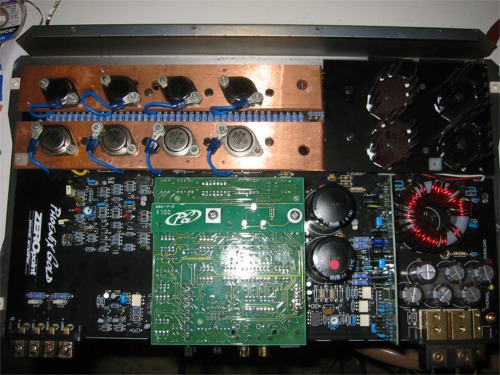
Later,
Jason
Posted: Sat Aug 23, 2008 1:10 pm
by nutxo
Im an expert on watercooling you know
You might be better off making channels in the copper and sandwiching 2 pieces together. Sold is pretty crappy for thermal transer and slathering compund on it would just make it messy.
It looks freakin great though. Very nice.
Posted: Sat Aug 23, 2008 3:53 pm
by Jacampb2
No, I didn't know that. One of the things I have considered is aluminum plates and machining a labyrinth of cooling passages in between two plates like you suggest. I don't have enough copper to do them in copper, so if I went that route, it would have to be aluminum.
My thoughts so far on this:
It was a lot more difficult than I figured it would be wire the transistors in the limited space I had. I originally had the collector lead on the bottom, and I just could not get the plate pulled down tight enough to still HS the bias transistors.
The copper I had is .25" thick, the original aluminum plates are .125" thick. This means that the fan is not going to sit properly, even when I get the PS plate made. It is going ot be .125"s to high on the inside. I think I am going to have to mill off the corner of the HS to get it down to .125.
The copper is way to heavy. Copper actually weighs a bit more than steel. When I put the board back in the case, you could see it visibly sag under the weight of the copper plates. .125" thick copper would be much better, but I am not going to buy more copper, it's to expensive. I will be doing the rest out of aluminum when I get to it.
So, here's the plan--
In all likely hood, I am going to do the 800.1's in aluminum. I am probably going to set up a DIY anodizing line so I can anodize the plates something other than black, and give it a little flair.
This is a ways out though, I want to put the Zx600 in service for a while, and make absolutely certain that it will be trouble free with the mods. I will hopefully be benching it into my 2 ohm dummy load tomorrow and see what it can make. I also need to scope it and reset the bias pots. After everything is checked good, I will be running it at 1ohm in my truck, with a single stroker 12. I will report back as soon as I know more.
Later,
Jason
Posted: Sun Aug 24, 2008 12:08 pm
by Jacampb2
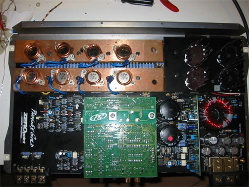
More today, but not much. I still may manage to get some testing done tonight, for now though it is family time.
I made some little heat pipes to wrap around the transistors. They should make a suitable heat sink for the time being. I was realy trying to get it ready for some low impedance testing, and ran out of time. I did finish making my dummy load. It consists of 10 50W 20 ohm power resistors in parallel, and two 50w 1 ohm power resistors in series. The sets can be wired in series or parallel or the big bank used alone, giving me a 2ohm load, a 4 ohm load, or a 1 ohm load. It is all built in a gallon paint can and filled with oil. According to the ham radio folks, the oil bath makes them good for about 10x their rated heat dissipation. If that's the case they should be able to take 5000 watts. I will take some pictures of the load later.
Here is a picture of the amp:
Later,
Jason
Posted: Thu Sep 25, 2008 2:34 am
by Jacampb2
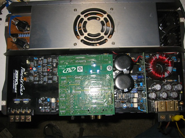
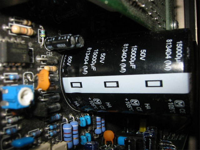
Okay, more progress, but no real time to talk about much at the moment. I have to head to work. Here is the progress so far. Added stand offs to support the heavier copper plates, re-routed wiring a bit to free up more room under the plates, added thermalloy to-3 top-hat style heat sinks, and lastly, trippled the rail capacitance. I am pretty sure the caps are going to be a smidgen to tall to fit in the case, but I have not tried to get it together yet.
Thats it for now, here are the pics:
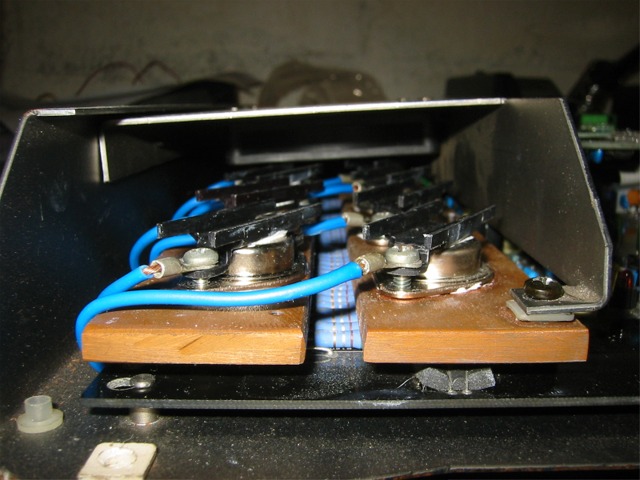
Later,
Jason
Posted: Thu Sep 25, 2008 3:24 am
by thedeal7235
not to sound stupid, but when you replace the caps, and increase them can that help for more power output, and if not, why do alot of you guys increase them ( for example my stock small caps are 2200uF, then i replace them to 4700uF?
Posted: Thu Sep 25, 2008 5:44 am
by stipud
Holy crap, that almost looks factory.
Those caps are huge