|
It is currently Mon Jan 25, 2021 4:41 am
|
View unanswered posts | View active topics
 |
|
 |
|
Author |
Message |
Jim Truett
|
Post subject: Power Supply capacitor replacement, an alternative technique  Posted: Sat Dec 13, 2008 12:14 am |
Joined: Tue Feb 06, 2007 9:07 pm Posts: 81
|
Far too often I see damaged amplifiers from improper repair. Here is one effective method to replace the rail capacitors in your PG amps without lifting traces on the PCB.
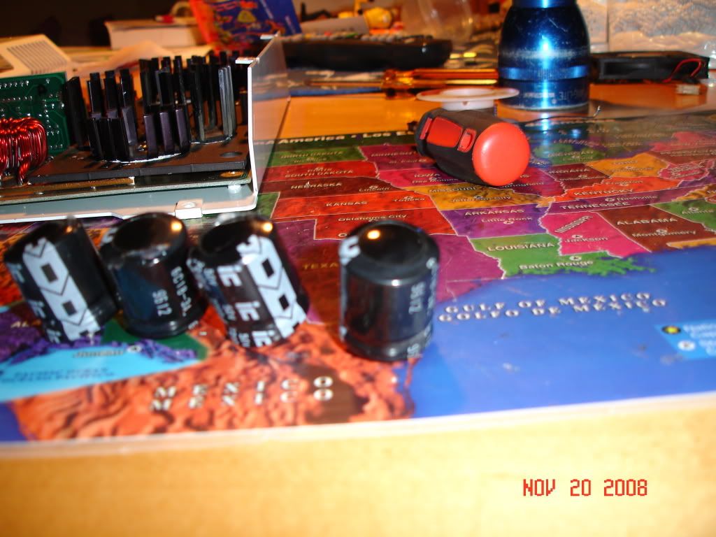
Starting with a $37 eBay special ZX350v.2:
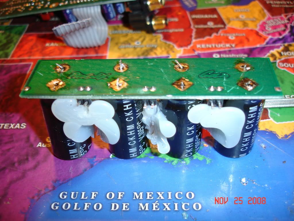
1. Get a pair of pliers and rip the leaking bastards right off of the board:
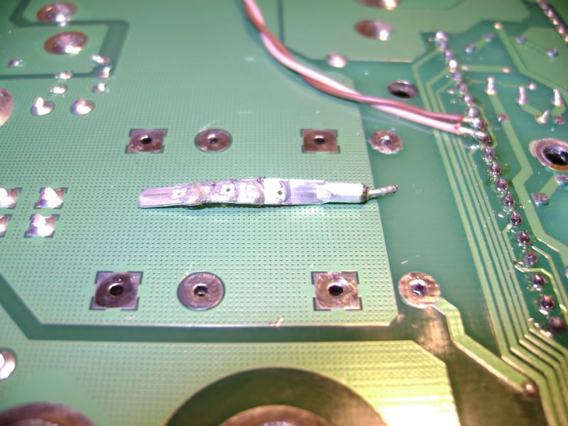
(Notice the two stray strands of copper wire that were hiding underneath)
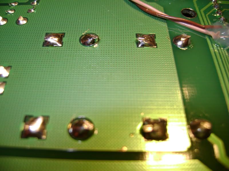
2. Flush cut the solder and leads (Spend the $5 and get a good pair of Xcelite cutters):
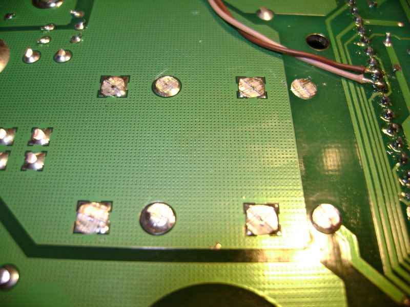
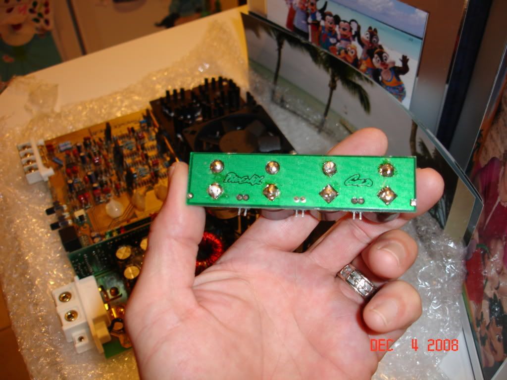
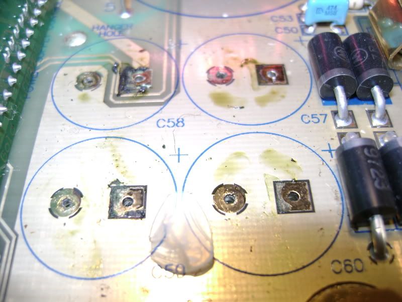
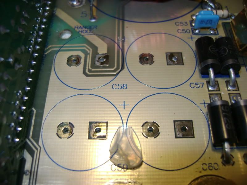
3. With pliers in one hand and soldering iron in the other, heat each pad while gently pulling the lead from the other side. After solder removal and cleaning you are left with this:
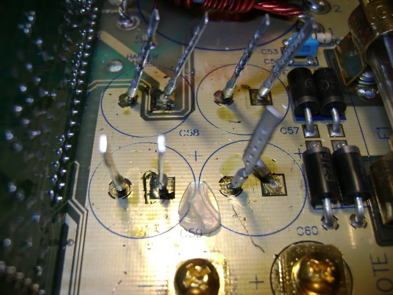
4. Clean up the mess. The electrolyte is acidic, and eats up the copper PCB traces:
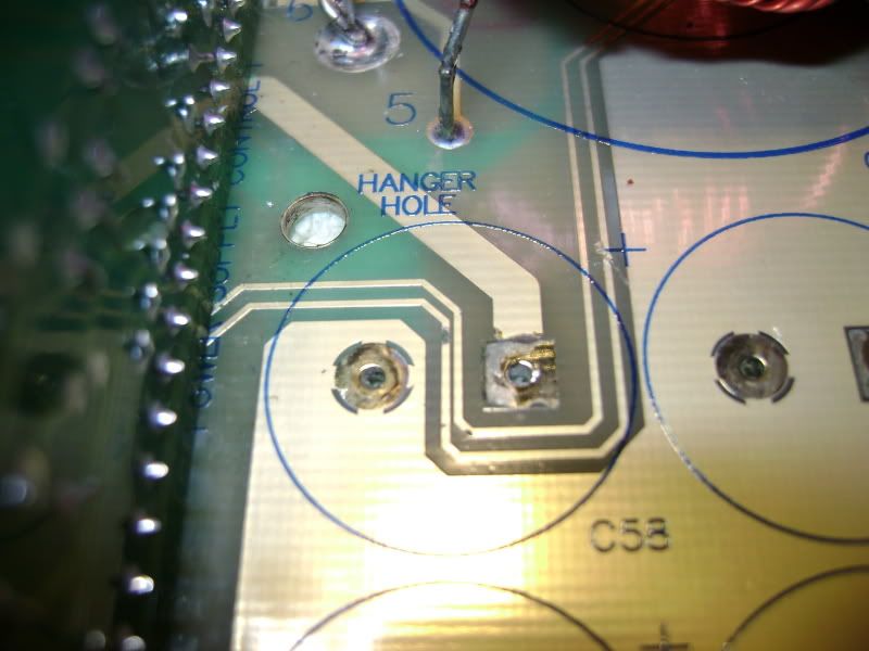
5. If you are wondering about the brown wires from a previous pic, look at the two thin traces. They are the MOSFET drive signal from the 3525 PWM controller. See where one is completely corroded through? That caused a runaway on one side of the power supply and smoked the FETs as well as the 3525.
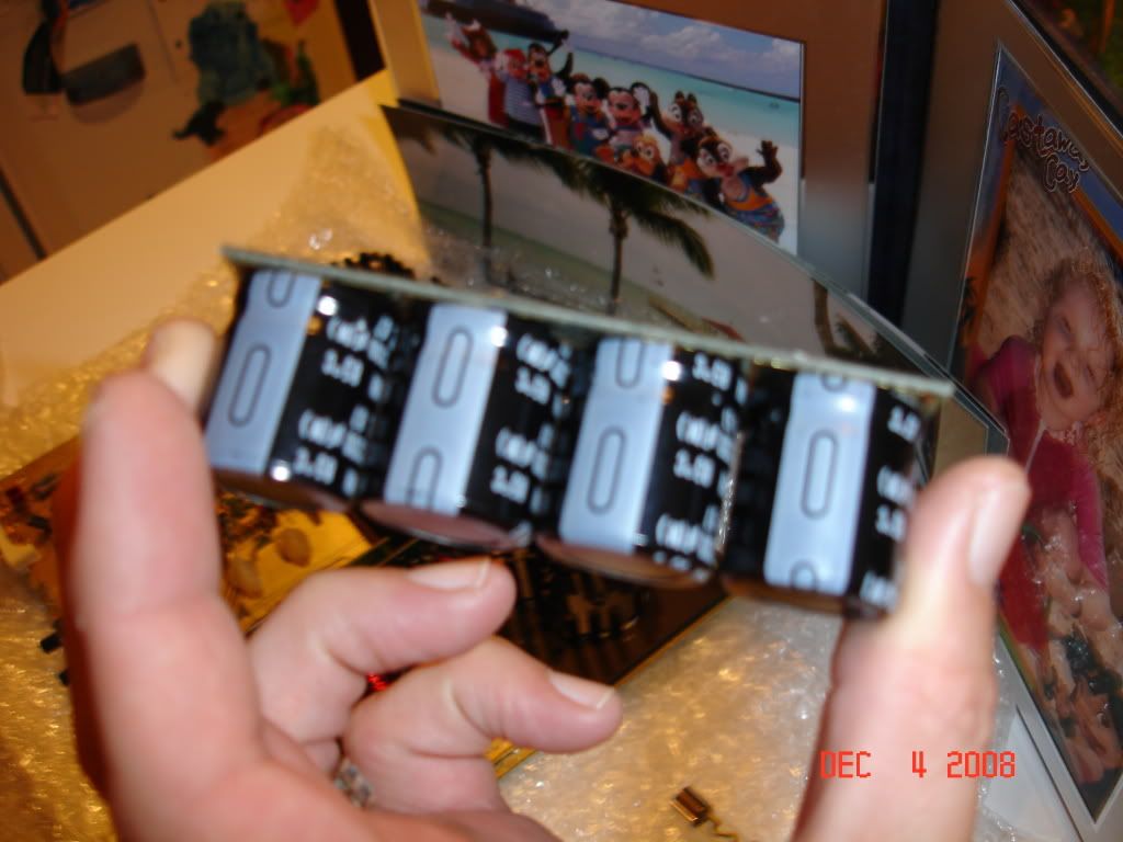
6. Solder in the new caps, and remove the flux residue:
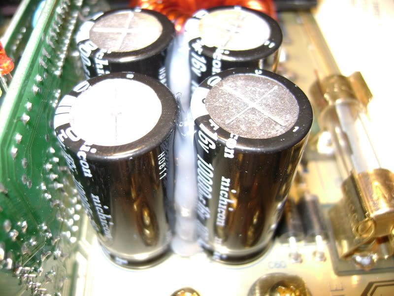
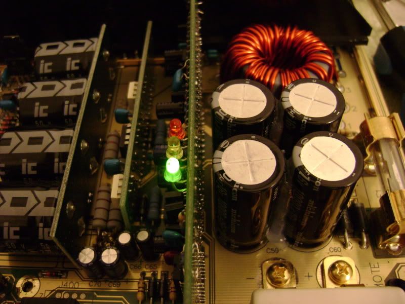
7. Enjoy:
The power supply rail caps cannot be removed the exact same way. They are "snap in" type, and the leads cannot be ripped out of them as easily. I just flush cut them on the solder side, then heat one lead at a time while gently pulling them away from the board.
|
|
|
|
 |
thedeal7235
|
Post subject:  Posted: Sat Dec 13, 2008 10:22 am |
Joined: Fri Jan 25, 2008 7:49 pm Posts: 1866 Location: Sanford, Florida(orlando area)
|
on mine, i de-solderd the rail cap" card", only 6 small solder areas to desolder on underneath of the board, thaT WAY theres alot more access to the rail caps on that model- and u can perfectly remove/replace the new ones , if necessary-mine were about 2 bursts-so i had no choice. on a zx450, u have ALOT more room-nice pics and explanation-
_________________ as she walked out the door she expressed, 'enjoy your amp addiction'
|
|
|
|
 |
oldskoolmseriesfan
|
Post subject: Re: Power Supply input capacitor replacement the right way  Posted: Sat Dec 13, 2008 12:15 pm |
Sherlock Homey |
 |
Joined: Sun Oct 19, 2008 10:03 pm Posts: 2517 Location: WEST SIIIIDE!!
|
Jim, thank you very much for the tutorial.That makes it very easy to understand and looks fool proof.This will make it so much easier to tackle my M25
|
|
|
|
 |
stipud
|
Post subject:  Posted: Sat Dec 13, 2008 1:16 pm |
Voltage Ohms |
 |
Joined: Sat Nov 26, 1983 4:00 am Posts: 14699 Location: Burnaby, BC
|
Interesting method! How much force do you have to apply to rip the caps out?
|
|
|
|
 |
thedeal7235
|
Post subject:  Posted: Sat Dec 13, 2008 2:07 pm |
Joined: Fri Jan 25, 2008 7:49 pm Posts: 1866 Location: Sanford, Florida(orlando area)
|
i just noticed u used 10,000Uf- ive never gone any higher than 4700Uf-Interesting-
_________________ as she walked out the door she expressed, 'enjoy your amp addiction'
|
|
|
|
 |
Jim Truett
|
Post subject:  Posted: Sat Dec 13, 2008 2:15 pm |
Joined: Tue Feb 06, 2007 9:07 pm Posts: 81
|
stipud wrote: Interesting method! How much force do you have to apply to rip the caps out?
Maybe 20 pounds or so.
|
|
|
|
 |
thedeal7235
|
Post subject: pics of my rail caps on my zx350  Posted: Sat Dec 13, 2008 3:20 pm |
Joined: Fri Jan 25, 2008 7:49 pm Posts: 1866 Location: Sanford, Florida(orlando area)
|
_________________ as she walked out the door she expressed, 'enjoy your amp addiction'
|
|
|
|
 |
diamondstar
|
Post subject:  Posted: Wed Mar 04, 2009 8:51 am |
Joined: Fri Nov 28, 2008 1:56 am Posts: 14
|
Sorry to bring this old thread back up, but did anybody find out how those 10000 uF caps got in there? I think the original ones are only 5600 ? I just got in a zx450 and would like to replace all the caps before I install it.
|
|
|
|
 |
oldskoolmseriesfan
|
Post subject:  Posted: Wed Mar 04, 2009 9:25 am |
Sherlock Homey |
 |
Joined: Sun Oct 19, 2008 10:03 pm Posts: 2517 Location: WEST SIIIIDE!!
|
So the 1000uf, 105*c are the caps I need for my M25 Tom?
_________________ Phorum PI!
Square woofers are GAY!!
|
|
|
|
 |
vin78
|
Post subject:  Posted: Wed Mar 04, 2009 9:34 am |
Vin Diesel |
 |
Joined: Fri Mar 02, 2007 3:49 pm Posts: 1373 Location: lalaland
|
I've used the 10000uf 85*c caps in the past (in Tom's link) w/o problems. They were for some of my MS amps though. I used the 5600uf (105*c) caps in all of my M's...
I spoke to some techs in the past and they told me that 85*c is acceptable.
|
|
|
|
 |
stipud
|
Post subject:  Posted: Wed Mar 04, 2009 9:57 am |
Voltage Ohms |
 |
Joined: Sat Nov 26, 1983 4:00 am Posts: 14699 Location: Burnaby, BC
|
oldskoolmseriesfan wrote: So the 1000uf, 105*c are the caps I need for my M25 Tom?
You want one of the two 5600uF's that I linked. The 10000uF cap is 85*C, which wouldn't be ideal for your M25. Not sure if it would fit vertically either; the ZX have quite a bit more vertical headroom. Vin, I am surprised you could fit the extra height of the caps in your MS!
The Panasonics are 2x the cost of the Nichicons, but have a 5x higher lifespan rating at 105*C (on paper). In theory this means you might not have to replace them as often. I suppose it depends on how long you will be keeping the amp. If you're bringing it to your grave, then the extra bit of money can't hurt.
These are the ones I just ordered for my MS2500:
http://search.digikey.com/scripts/DkSea ... e=P6667-ND
http://search.digikey.com/scripts/DkSea ... =P11210-ND
|
|
|
|
 |
vin78
|
Post subject:  Posted: Wed Mar 04, 2009 10:17 am |
Vin Diesel |
 |
Joined: Fri Mar 02, 2007 3:49 pm Posts: 1373 Location: lalaland
|
stipud wrote: Vin, I am surprised you could fit the extra height of the caps in your MS!
The length of that cap is the same as the OE caps in original MS amps, both are longer then the 5600uf caps iirc.
I actually bought my 10k uf caps on ebay. I ended up giving them away to a friend.
|
|
|
|
 |
stipud
|
Post subject:  Posted: Wed Mar 04, 2009 10:32 am |
Voltage Ohms |
 |
Joined: Sat Nov 26, 1983 4:00 am Posts: 14699 Location: Burnaby, BC
|
Interesting. I measured my input caps at ~31mm, and they looked to be close enough to the top that I didn't want to risk anything larger. Unfortunate, because I probably could have gotten more capacitance. Oh well.
|
|
|
|
 |
bogart
|
Post subject:  Posted: Wed Jun 24, 2009 9:52 am |
Joined: Thu Dec 18, 2008 6:30 pm Posts: 1533 Location: SE PORTLAND
|
I tried this method last night when I stripped the caps out of an m50...it is just as easy...think that just desoldering the caps is just as quick and less clean up....
i personally, knock on wood, havn't lifted the pads on anything....not to sure how you could without flagrantly tearing stuff out and nothing seems to get excessively hot anywhere while desoldering...just seems basic
|
|
|
|
 |
CraigsMax01
|
Post subject:  Posted: Tue Aug 25, 2009 8:07 pm |
Joined: Mon Aug 24, 2009 6:13 pm Posts: 20
|
how were those damaged traces fixed?
|
|
|
|
 |
|
|
 |
|
 |
|
You cannot post new topics in this forum You cannot reply to topics in this forum You cannot edit your posts in this forum You cannot delete your posts in this forum You cannot post attachments in this forum
|
|