damn, that sucks then cause I've had 3 different sets of SSMB8s (6 woofers in total), and they all have done the same thing.
I'll post pics when I get home.
97 Maxima Install - Being Redone

okay, correction on everything above...
I was working on my car on Friday and decided to look at the speaker with my bro again. The spider is connected to the cone. The actual speaker actually bottoms out too soon is why it's making that slapping noise. It hits the magnet at the bottom.
More pics to come when I get a chance... right now trying to figure out why the hell my crap doesn't stop wining (hearing engine noise). Going through the steps to figure out why, but I have a good feeling the ground is too close to the car's ECU... haven't had that much time to try all the steps in the how-to yet.
So I spent a lot of time yesterday making these custom 9" brackets fit the Maxima. Everything that could go wrong, basically did, and in the end, it took 7 hours to get 2 brackets done!!! Was much easier to do the second one after I figured out exactly what was needed when I made the first one.
Pictures below:
Pictures below:
- Attachments
-
- Cutting the insides first helps out a lot so you don't have to hold the board while cutting.
- Small 9 Bracket Sketch 2 small.JPG (40.43 KiB) Viewed 12525 times
-
- Plotted the 1/4" from the 3/4" which was previously plotted from the original 9" mounts and then custom cut till it "fit".
- Small 9 Bracket Sketch small.JPG (51.73 KiB) Viewed 12525 times
-
- A shot of the 3/4" MDF bracket alone.
- Big 9 Bracket small.JPG (39.49 KiB) Viewed 12525 times
-
- Made the 3/4" MDF brackets from the cutout holes when I originally created my box for the TI12D Elites.
- Big 9 Bracket 2 small.JPG (39.16 KiB) Viewed 12525 times
-
- Here's a shot of the three brackets (2 1/4" and 1 3/4"). The 1/4" brackets have bigger holes made from the bigger drill bit wihle the 3/4" bracket has a smaller hole so the screw can clamp all three together without any gap from the s
- 9 Bracket Setup Small.JPG (51.92 KiB) Viewed 12526 times
For some reason, the comments were cut on the last picture:
Here's a shot of the three brackets (2 1/4" and 1 3/4"). The 1/4" brackets have bigger holes made from the bigger drill bit wihle the 3/4" bracket has a smaller hole so the screw can clamp all three together without any gap from the screw threads. I know, I destroyed the big drill bit, but that's all I had and was going to work with it till it broke. I basically burned the holes through towards the end. Thank god it didn't break.
Here's a shot of the three brackets (2 1/4" and 1 3/4"). The 1/4" brackets have bigger holes made from the bigger drill bit wihle the 3/4" bracket has a smaller hole so the screw can clamp all three together without any gap from the screw threads. I know, I destroyed the big drill bit, but that's all I had and was going to work with it till it broke. I basically burned the holes through towards the end. Thank god it didn't break.
I then needed to glue the three pieces together to make 1 bracket:
- Attachments
-
- After putting glue on each layer, I screwed it in using the holes where the speaker will be screwed to so it clamps everything together.
- 9 Bracket Glued small.JPG (42.18 KiB) Viewed 12523 times
-
- Here's everything glued together... letting it stick for the night before putting it in the car.
- 9 Bracket Glued 2 small.JPG (39.67 KiB) Viewed 12523 times
As you can see from the pic above, the 8 screws that are in right now are meant to hold the speaker to the bracket and the 4 holes that have no screws are meant to hold the bracket to the door.
If you're wondering why I used a 3/4" and 2 1/4" brackets, your answer is test and trial. I originally wanted to just use a 3/4" bracket and put the speakers in the car. That didn't work because the door hole is too small (designed for 6.5" speakers, so I had to push the 9" further out. I figured I'll buy a sheet of 1/4" mdf in case just a 3/4" and 1/4" (1" MDF total) made the speaker fit, but that didn't work either. In case that didn't work, I would just cut another 1/4" out instead of buying another sheet of 1/2" MDF and use that.
I was trying to be very conscious that the speaker does not hit the door panel (which it does now, so there's gonna be cutting there too), that's why I wanted the mount as shallow as possible.
I'll be back to work on this tonight after work to mount the speakers into the doors. I unfortunately have to cut the door slightly to make the speaker terminals fit and cut a flap off the inner door panel so the mounted speaker does not slap against the door panel.
More pictures to come...
Also, after much trial and error, I got the TI6 Elites to sound "perfect" with a high pass filter @ 100 Hz, and each speaker pushing 200 watts, using the passive crossovers. I got 100 Hz from trying different songs and moving the frequency around until the bass was not hitting sloppy, but was still hitting hard. I then counted the clicks on the x200.4 and saw that it was set to 99 Hz.
Now, the TI9 manual says to cross them at 150 Hz when using the TI9-5-1 setup. The high crossing is probably because the 5.25" cannot dig as deep as the 6.5" speakers, so the TI9's have to make up for it. Since the 6" can go to 100 Hz, should I cross the 9"'s at 100 Hz, or at 150 Hz? The 9" are going to receive 400 watts per side.
Also, the manual says they should run bandpass 40-150, but I don't think I can do that with TI400.2's (which will power these). I am basically going to run two y-splitters from the output of the x200.4 to 2 TI400.2's (ran bridged) so I can maintain stereo on the TI9's. Anyone have any ideas on how to run them bandpass? Is there a need to run the bandpass, will the 9" be damaged if I am pushing 400 watts to them without a HPF @ 40 Hz?
So here's the work I did last night after work:
- Attachments
-
- Here's the 9 in the door before the door panel goes on
- In Door Open small.JPG (59.47 KiB) Viewed 12503 times
-
- A close look at the 9 installed in the door
- In Door Open Close small.JPG (61.52 KiB) Viewed 12503 times
-
- Bracket put on before 9
- Bracket In Door small.JPG (73.81 KiB) Viewed 12503 times
-
- The door after it's cut
- Door Cut small.JPG (68.5 KiB) Viewed 12503 times
-
- So I had to cut a piece of the door to fit the terminals of the speaker. Here's where it's marked.
- Door Marked small.JPG (72.95 KiB) Viewed 12503 times
More Pics:
- Attachments
-
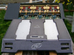
- This is the mess in the trunk right now. Most of these wires are actually being used, just extra long so I can set it up when I'm done without needing new wires. I promise, this will look better, lol.
- Amp Mess small.JPG (48.31 KiB) Viewed 12502 times
-
- The 9-6-1 set
- 9-6-1 small.JPG (51.33 KiB) Viewed 12502 times
-
- Close up view of the 9 inside the door panel
- In Door Close small.JPG (50.34 KiB) Viewed 12502 times
-
- Here it is with the panel on. I left the grill off so I can see if it's gonna hit anything. Grill will go on later.
- In Door small.JPG (37.8 KiB) Viewed 12502 times
so after testing this while driving to work today, I think I need to cut some of the door panel off so the speaker does not hit the panel. I'm not sure if this is going to resolve the problem. I had no idea this speaker would move so much on the hard bass hits @ 400 watts. It's still breaking in too, meaning it's gonna move even more!!!
I might have to cut more of the door metal (which I really don't wanna do) and use just a 3/4" (maybe with 1 1/4") bracket so it's not out as far.
Why is this being so difficult!?!
I might have to cut more of the door metal (which I really don't wanna do) and use just a 3/4" (maybe with 1 1/4") bracket so it's not out as far.
Why is this being so difficult!?!
Because yer putting a fukin 9" speaker in the door of yer car..... 
Those tender little burgers with them little, itty-bitty grilled onions that just explode in ya mouth like flavor crystals every time you bite into one.. just makes me want to burn this muthafuka down.... Come on, Pookie, let's burn this muthafuka down!!!

What do you recommend I do to get them in bandpass? My current setup right now is from the HU, to the TLD66 line driver, to the x200.4, y-split to 2 TI400.2 amps.
I really don't want to get an external active crossover because 1) don't have any more money to spend and 2) have no idea where to put them... I already gotta figure out how to put 4 amps, the powercore and a huge box back there.
I can replace the 2 TI400.2 amps with a TI800.1 and run the subsonic filter on that, but I'd have to sacrifice stereo.
Ugh, so pissed.
If you had Ti amps instead of Xenons, you would set the crossover to highpass at 150Hz for the mids, then send the lowpass remainder of that signal through the aux-out to the 400.2, which is set to highpass at 50Hz. Or with a Ti sub amp set the lowpass crossover at 50Hz and send the highpass remainder to the 400.2, which is set to low-pass at 150Hz.maka78 wrote:I'm powering the TI9s with TI400.2 amps. I don't know of any way I can use the crossovers on the TI amps to get bandpass. They have lowpass, highpass, bypass.
Aux outputs on Xenons are full range, you can't take the signal after the crossover unfortunately. So this configuration is impossible

If its a X-over you need try and pick this one by zapco SLX-4 it will do just about anything. there is one on the bay right now but you will need the PS and rca to SymbiLink conversion connectors.
http://www.zapco.com/prod/pdf/slx4.pdf
$75.00 as of this posting no bids
http://cgi.ebay.com/zapco-slx-4_W0QQite ... 240%3A1318
What is the SLX-4?
The SLX-4 is a six-way four output electronic crossover. An
unprecedented amount of flexibility has been designed into this unit allowing
configuration for practically any system. Featuring SymbiLink™ balanced
inputs and outputs, the SLX-4 embodies the total dedication to sonic fidelity
that has made ZAPCO famous around the world.
The SLX-4 has four main outputs that can be configured as follows:
X1 output:
High pass output. This output can also tie into the X3 crossover for
use in high frequency applications.
X2/X3 output:
High pass or band pass output. A circuit board mounted switch
selects between the two modes.
X4/X5 output:
Low pass or band pass output. This output also has the mode
switch.
X6 output:
Low pass output for the woofer. The low pass out may be set to
stereo or to sum-mono. It may also be set to either 12dB/octave or
24dB/octave.
Any output can be fed from either the front or the rear input. This
option allows front/rear fading or daisy-chaining capability.
“Slave” outputs supply the same signal that is fed into the input. The
front input feeds the front slave output and the rear input feeds the rear
slave output.
If the SLX-4 that you have purchased is to be used in a system in
which no Zapco SymbiLink™ amplifiers are to be used, a Zapco PSI-HPSL
will need to be used to power the SLX-4.
62
Key Features
• SymbiLink™ balanced inputs and outputs
• Individual variable crossover points
• Dual input capability
• Slave outputs for easy system expansion
• 12/24dB per octave options for low pass
• No external power wiring necessary when used with a SymbiLink™
amplifier
• High signal voltage capability
• LED clipping indicator
• Dashboard or trunk mountable
• Gold plated signal connectors
• Available in white or black
• Quality ZAPCO construction
• Designed and manufactured in the U.S.A