Problem with MS2250
Problem with MS2250
I replaced all the caps on my 2 MS2250 boards i need for my DFAS. One of them is working fine now but on the other one C309 gets hot and blows after 30 seconds when i turn it on. 
- Attachments
-
- DSC01629.JPG (101.23 KiB) Viewed 6059 times
Music is silver, PHOENIX is GOLD
-
spiritofnorway
- Posts: 374
- Joined: Sat Oct 25, 2008 9:17 am
- Location: Salzburg, Austria
-
mhyde71

- Dr. Jekyll
- Posts: 6231
- Joined: Sun Jan 20, 2008 8:34 pm
- Location: PG FanBoy in Green Mtn Vermont
- Contact:
joerg, might wish to check the via's for the caps... and make certain that no via's got burned/pulled out or something... and all caps are correct in their placement- neg to neg pos to pos etc...?
I dunno... vias, traces, or polarity i would be inclined to think, if it worked prior to.
Incidentally, all your 2250 burnt board stuff has been out and sitting in bag ready for next shipment (did it last weekend, meant to tell you this past week)
I dunno... vias, traces, or polarity i would be inclined to think, if it worked prior to.
Incidentally, all your 2250 burnt board stuff has been out and sitting in bag ready for next shipment (did it last weekend, meant to tell you this past week)
PAST WORK/S HERE::
https://www.facebook.com/KhameleonKoatings/photos_albums
https://www.facebook.com/KhameleonKoatings/photos_albums
Will double check again but couldn´t find a mistake the first time!mhyde71 wrote:joerg, might wish to check the via's for the caps... and make certain that no via's got burned/pulled out or something... and all caps are correct in their placement- neg to neg pos to pos etc...?
I dunno... vias, traces, or polarity i would be inclined to think, if it worked prior to.
Incidentally, all your 2250 burnt board stuff has been out and sitting in bag ready for next shipment (did it last weekend, meant to tell you this past week)
Thanks for taking all the stuff out of the damaged board
Music is silver, PHOENIX is GOLD

Ok, so you never replaced the cap that is blowing, it just started blowing after the replacement of the other caps?
It sounds to me like you damaged a via under the rail caps. They are very easy to damage when replacing the caps, and if broken you will loose conduction from one side of the board to the other. This causes a whole host of problems and may have damaged other components beyond just this cap.
So far on every single MS amp I have worked on where someone has already replaced the rail caps, they have damaged the vias doing so.
-
mhyde71
- Dr. Jekyll
- Posts: 6231
- Joined: Sun Jan 20, 2008 8:34 pm
- Location: PG FanBoy in Green Mtn Vermont
- Contact:
vias can be fixed, but like ^^^ said it can cause another host of issues. but/so I would start w/ by checking the vias, HOW you ask i dunno w/o taking the caps out again... but you would prolly want to gob up on solder on the cap (or trace itself) so it can make connection to the trace that the via would have made if it was there.... does that make sense joerg... can be fixed, but the via that is in trouble (providing it is a via), the cap(or caps) need to make connection to the trace(s) that they would have given the via(s) were/are intact.
eric can re-iterate or correct me on this, but that would be my guess/direction... what say you eric... right? if via is gone/burnt or whatever, the cap needs to be in contact with that trace that the via would have connected it to..
eric can re-iterate or correct me on this, but that would be my guess/direction... what say you eric... right? if via is gone/burnt or whatever, the cap needs to be in contact with that trace that the via would have connected it to..
PAST WORK/S HERE::
https://www.facebook.com/KhameleonKoatings/photos_albums
https://www.facebook.com/KhameleonKoatings/photos_albums
I just checked everything again and managed to find absolutely nothing! I had the brilliant idea to take C309 out and meassure voltage on it. 
When powering the board up it made a cracking noice and a few of the transistors got hot as hell. Now the right channel doesn´t work anymore

Anybody in here that can repair this board for me
When powering the board up it made a cracking noice and a few of the transistors got hot as hell. Now the right channel doesn´t work anymore
Anybody in here that can repair this board for me
Music is silver, PHOENIX is GOLD
Fixing a via is not a matter of putting more solder on it. The solder will never wick far enough down to contact the pad on the other side.
To fix these large snap in caps you need to either drill a small hole next to the via and run a tiny wire from one side to the other, or I have also had luck putting some solder wick in the hole with the cap lead then soldering it. Either way you need to find where the top pad goes and make note of it. Then check resistance from that point to the bottom pad. It should be 0 ohms or close too it when the cap is installed.
What transistors got hot as hell? I hope it was not the output transistors. You should have the amp mounted in the heatsink when doing this or you can fry the outputs.
I am nearly certain this is a broken via problem. On one side of that cap should be 64V, on the other should be 58V, this is only a 6V difference. The cap is rated at 25V. If the via is broken you possibly remove the 58V, so now there would be 64V across that 25V rated cap, which will fry the cap.
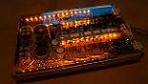
The green marked cap is the one that had the problems first (C309). I was able to get a volate reading of 35Volts with a DMM. But this cap is only rated at 5 volts.
After that i took C309 out of the board and wanted to test again to make sure i really got 35Volts there.
After a minute or so i heard the cracking sound and removed power supply real quick and noticed that the red marked transistors were very hot.
I tried to power it up again and the red leds on this side won´t turn on anymore now.
- Attachments
-
- DSC01632.JPG (95.8 KiB) Viewed 5969 times
Music is silver, PHOENIX is GOLD
The 4 transistors on the left of the 6 you circled are the power supply FETs for that channel. If the problem is on the cap you circled, this is the other channel, so clearly you have a problem on both channels.
If a via is broke and you are missing power to one half of the top channel, it will not light the two LEDs on the board, and the channel will draw significant current, which will heat up those transistors you circled.
Replace the small capacitor which has failed. Remove the 4 big blue capacitors and clean up the holes as best you can. Post the best detailed photos of those holes as you can here.
-
mhyde71
- Dr. Jekyll
- Posts: 6231
- Joined: Sun Jan 20, 2008 8:34 pm
- Location: PG FanBoy in Green Mtn Vermont
- Contact:
okay very good i stand corrected, and yes it was kinda off the cuff,
prolly should have kept mouth closed...
It's almost kinda like a reading half of the first aid book, you'll end up doing more damage than good knowing only half of something of this nature.
BUT to explain myself, i was thinking that if the cap is not getting in touch with the trace that it needs to, (from the underside) and up through the via to the top side... Thinking that the it is tip of the leg that connects to the trace on the underside that comes through the via then up to the top part of the board. AND if there was/had been some break in that it would be possible to build up some solder on the cap/caps leg to touch/connect to the trace on the top side of the board versus the bottom first, up through via and then onto the top....
BUT please and thank you for getting joerg back on track.
@ joerg I got your PM, just stopped in for dinner at home, and walking back over to shop- only phone with so wanted to let you know i got your PM, and will do. and will get back AND lyk
matt
PAST WORK/S HERE::
https://www.facebook.com/KhameleonKoatings/photos_albums
https://www.facebook.com/KhameleonKoatings/photos_albums
I am working on this amp for joerg. Damaged vias were to blame for his problems. If anyone has similar issues to these, double check your vias. The problem is not nearly as critical on the input supply caps as it is on the rail caps. When the top side of the board is not connected to the rail caps, only some portions of the amp receive rail voltage. This puts excessive voltage across a lot of parts and they fail.

Hi, I replaced caps on about six M and an MS amp ages ago after reading a thread on here. I never experienced any problems and they all worked perfectly afterwards. However, it was concerning reading your comments Eric, regarding some issues you've come across with repairs. In your opinion, what are some people doing so they damage these amps? Are they overheating by slow soldering work, or something else I can watch out for?!