Help with some MS275's identifying acouple parts inside it
Help with some MS275's identifying acouple parts inside it
OK I got acouple MS275's and I am just wonderig what the 2 switches on the inside are. They are not in the manual. This is a revision F board and other than that all it says it 1990 on it. I will try to get acouple pics up later but I would think some of the MS fanatics will know what they do.

item
I think the one switch with the yellow dot is a high current low current switch. it will lower the amount of current if you are running 2 ohm bridged
it was made to make the amp last longer with less heat under heavy load
it was made to make the amp last longer with less heat under heavy load
most of my gear is gone :liar:
2020 honda accord sport
2020 honda accord sport
-
NewOldStock

- Posts: 678
- Joined: Sat Nov 21, 2009 10:07 am
- Location: SW Washington
-
NewOldStock
- Posts: 678
- Joined: Sat Nov 21, 2009 10:07 am
- Location: SW Washington
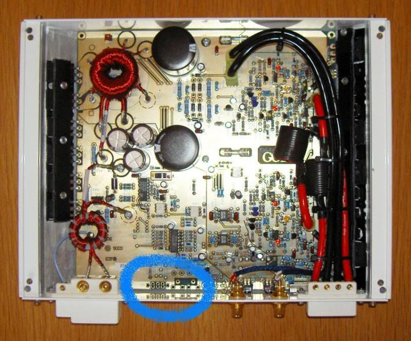
at the edge of that blue circle - where the black line is - there are 2 holes at the bottom and 2 holes above that black line - thats where the master/slave connections attach.scottn29 wrote:This is where the other switch is, and Shaheen I think it is blue on 1 side, I dont see it on all the amps. This is where it goes (pic was stolen from Kub), I got the amp in my backseat right now so I cant look at it till I leave work
I am pretty sure the 6 holes next to it are where the other switch is. Mine does have the master/slave connectors thereNewOldStock wrote:at the edge of that blue circle - where the black line is - there are 2 holes at the bottom and 2 holes above that black line - thats where the master/slave connections attach.scottn29 wrote:This is where the other switch is, and Shaheen I think it is blue on 1 side, I dont see it on all the amps. This is where it goes (pic was stolen from Kub), I got the amp in my backseat right now so I cant look at it till I leave work
yeah , then its for the master slave switch , back in the day you would pick up noise if you had the amps in master slave settings. So they had this switch . it the same one they had in the original MS2125
This is from the FAQ
What does the internal blue switch do on my MS and MPS series amps??
Early MS275s (as well as other early MS series amplifiers) had another two-position switch on the circuit board with a blue dot next to it. This is the Master/Slave switch. The standard position is towards the blue dot, which is the slave position. There are two 1/8" mono phono jacks for connecting amplifiers together located on the amplifier's end panel. The Master/Slave switch configures the amp as either the master or slave in a multiple amp installation. One amplifier is designated as the master amp with all others as slaves. This allows the master amplifier to control power supply switching for all amps. By switching all power supplies in sync, AM radio performance is improved by eliminating heterodyne noise. However, if connected and configured incorrectly, power supply damage to all amplifier power supplies is highly probable. For this reason, we eliminated this feature on later model MS amplifiers. The switch can be in either position and has no effect on performance if this feature is not used.
What does the internal Yellow/Red switch do on my MS275?
All MS275s have a two-position switch in the middle of the circuit board with a red dot on one side and a yellow dot on the other. At the factory, the switch is set to the yellow position. The red position will limit the power supply voltage and allow for more output current. This can improve thermal performance when the amplifier is driving low impedance loads (2 ohms bridged). This offers an alternative to installing cooling fans.
AKA Shaheenk

OK looks like The MS275 revision F I have has the 2 switches on the board, the other I have come to find out is a MS250, the board is alittle different with some extra cap for the PS and it has different transistors. It has the same switches as the MS275, so not all revision F's are lacking the switches.
Thanks for the help guys, its was useful as I had to make sure the switches were in the correct position for bench testing
Thanks for the help guys, its was useful as I had to make sure the switches were in the correct position for bench testing