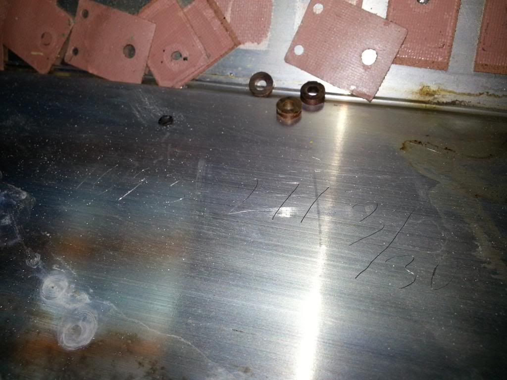
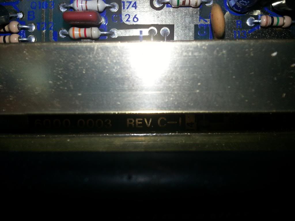
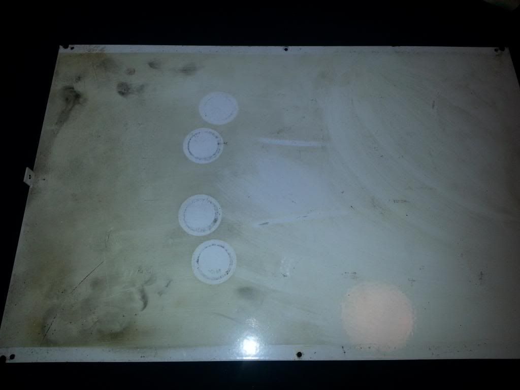
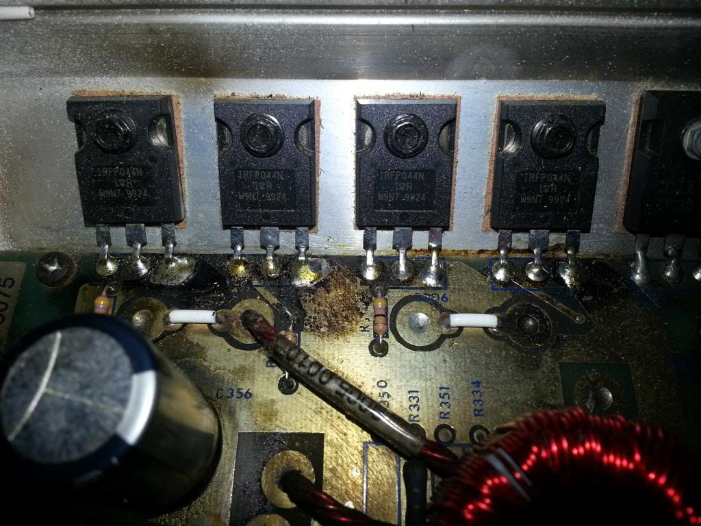
This particular amp was bought off a co-worker while I did car audio in high school about 12 years ago. He said it had blown up and sent it back to PG for repair, and he had used it in an SPL car for many years after that before I bought it, but not very frequently. I have no idea if the caps are all original, but seeing that the input caps are leaking badly, I figured they were. There is a smoke image on the bottom of the cover, and it looks like a FET blew out originally, not a cap, since the board doesnt seem to have any damage. (see pics). I have used this amp in 5-6 different cars over the years, without any problems except the buss bars.
Well i figured out the problem with the amp turning on and off, the remote wire on the inside part of the connecting block worked it way loose. Im sure it doesnt help that the amp was mounted to the box, but I will be redoing that after the caps are done.
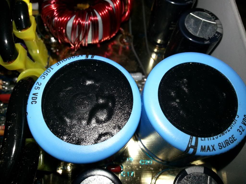
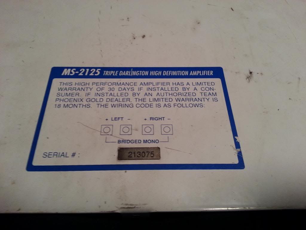
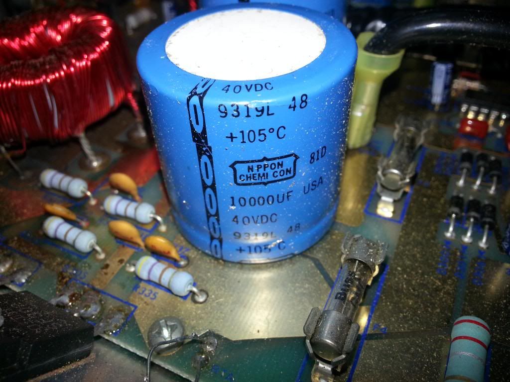
I have read on here that the MS2125 uses 50V rail caps, but mine are rated at 40V, and 10000uf, 105C. Im working on ordering parts to do all 3 amps ASAP, and wanted to know if someone had a DEFINITIVE answer on what the voltage reading should be. Im not sure if the rail caps have ever been done.
Im going to buy these for my input caps :493-1545-ND from digikey. at 35.5mm tall they are pushing the normal height limit, but i measured with a dial caliper and there is 37mm from board surface to bottom plate.
So is it 40V for rail caps, or 50V, and is there a particular part number you guys like to use? Ive seen a lot of topics like this but I want to know 100% before I do this to all my amps. I know the 275 might use different parts but I havent taken it out of the car yet.
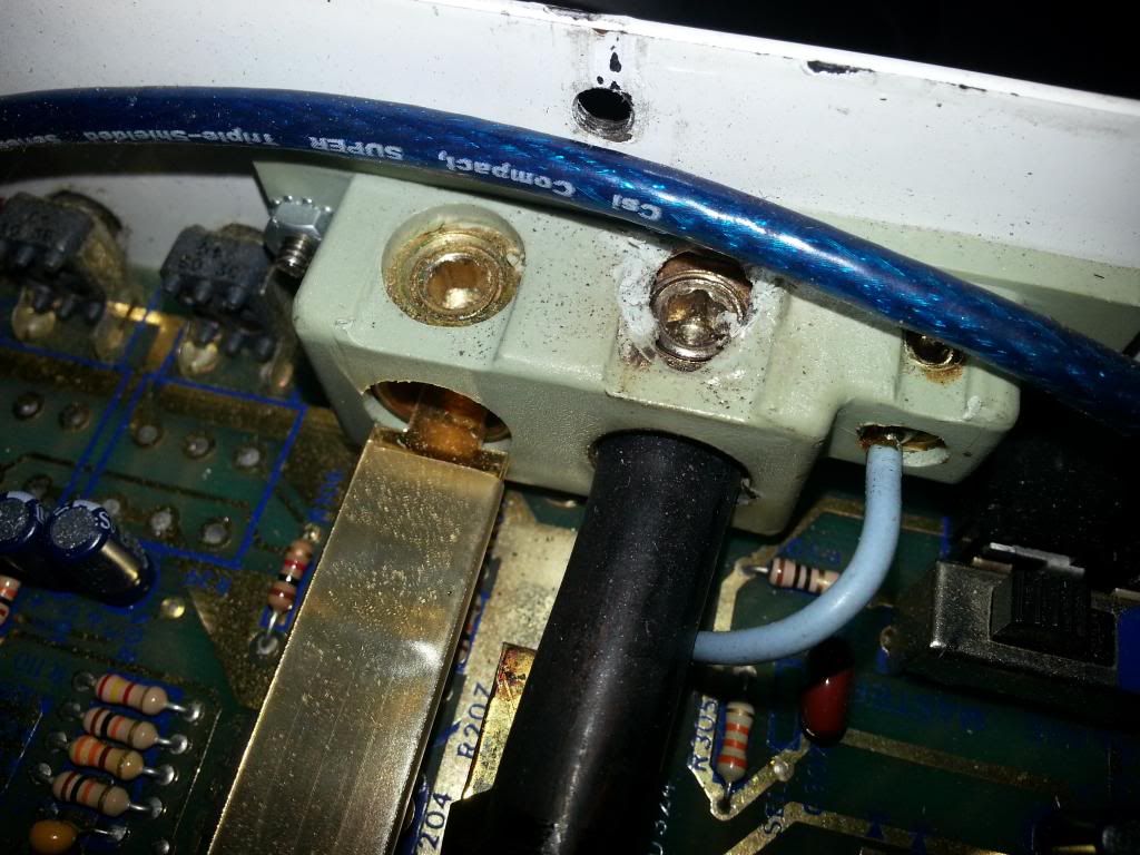
Second question. With a 200A shunt meter hooked to the amp power leads, coming from a 2600 series Kinetic battery, with 0ga to a 10Farad cap, and GOOD 4ga going to the 2125, ive gotten readings of almost 175A sustained from current flow. I know there is supposed to be 2 40A fuses inside, mine has 50A (ive never replaced them so IDK). Does this seem possible. I know during peaks when the caps have to charge they will pull a lot of current, but I would think 100A would be my limit without blowing the fuses. Even before the shunt meter, I could pop a 150A blade fuse with a good deep bass song. Im assuming this is why I blew through one of the bus bars, twice. The that goes into the terminal block actually got so hot where it necks down it melted, and melted the block inside the plastic too. See pics. Is there an upgrade or a way to run 4ga (or hell even 0ga) directly to the board. Less transitions and connections the better I would think!
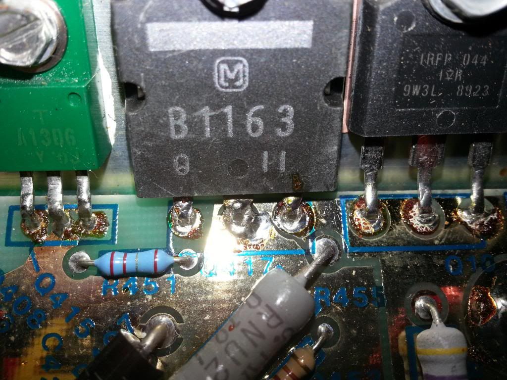
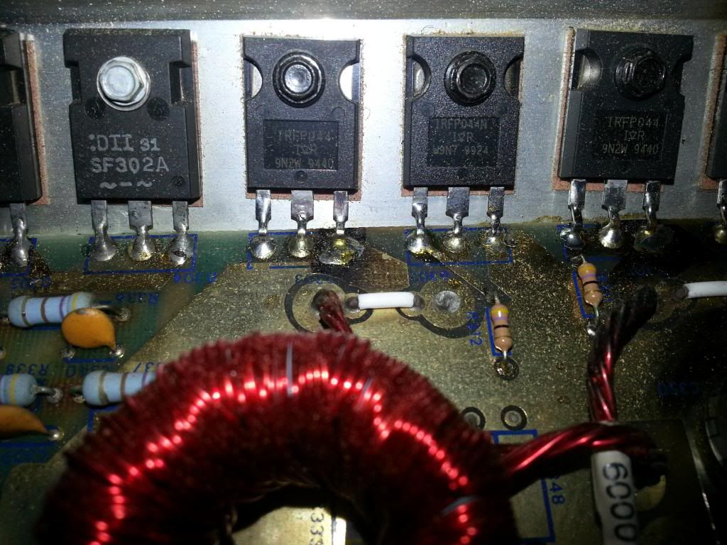
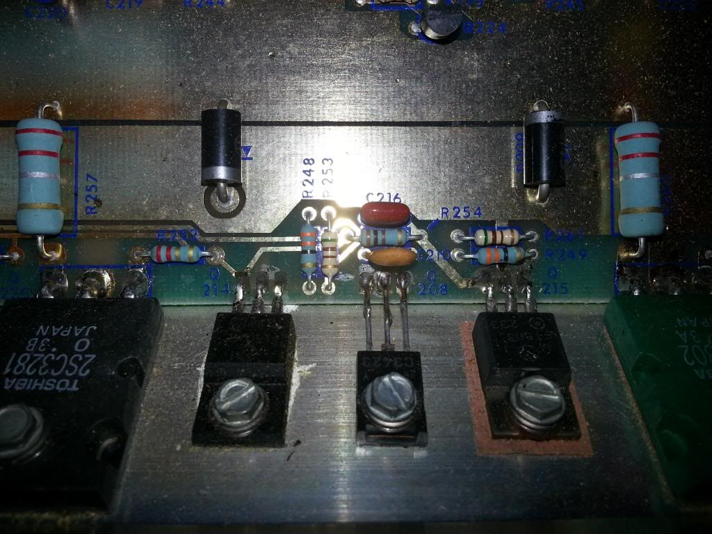
Another side note (i know a lot of questions). Ive seen a few of these that have a transistor piggybacked on another transistor in the middle of the heatsink. What revisions is this on? It looks like mine might have had those piggybacked ones at some point, but were removed? Any help would be great.
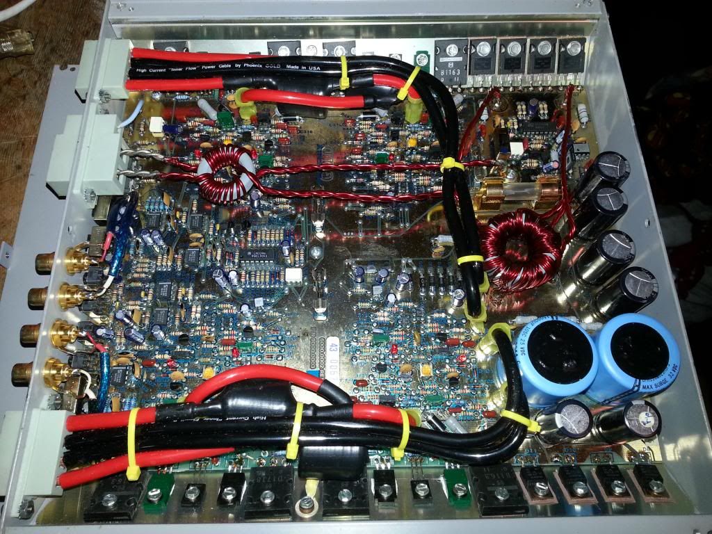
Ok now for some pics:
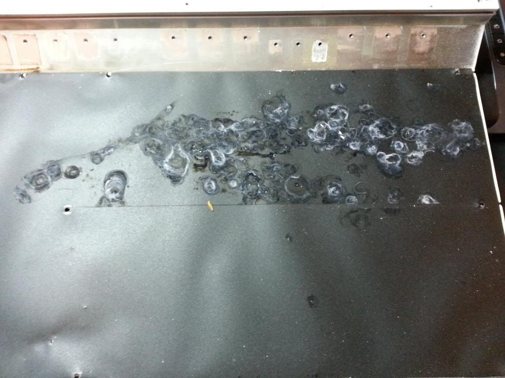
inside smoke damage and possibly where the FETS went bad before
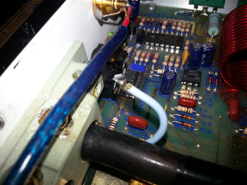
electrolyte damage on the input caps, and pics of the ratings
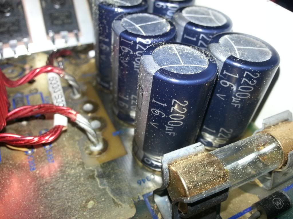
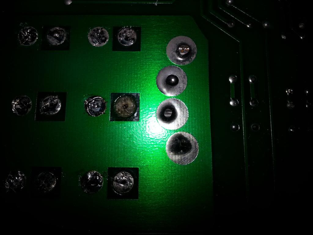
rail caps
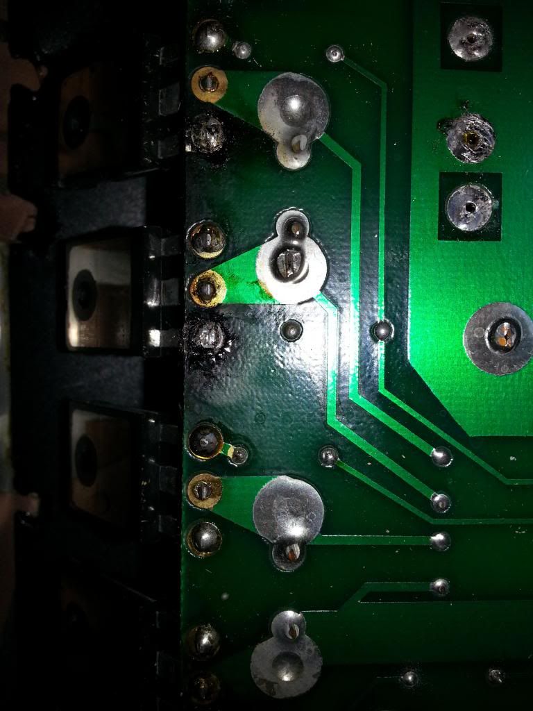
bad buss bar
transistor piggyback maybe? 3 globs of solder in the middle of the lead makes me curious
and finally, the loose damn remote wire. but not finding this and blowing a cap would have totally ruined my day.