Why is my d-block displaying the "LO." to the RMD I have.
Before thinking that maybe the RMD is defective, we also tried Joergs RMD he had with him. SAME RESULTS... what and why is this happening? Anyone ever seen that before?? Or have thoughts/ideas as to what/why the issue is???
I have two other meters in car and hand held (DMM) and everywhere i go i get 13.8, 14.1, 13.2, etc... so why the reading of "LO"??? dont get it...
Any help would be great!
see pic's
Pls thx
TiRMD / Ti D-Block Issues???
-
mhyde71

- Dr. Jekyll
- Posts: 6231
- Joined: Sun Jan 20, 2008 8:34 pm
- Location: PG FanBoy in Green Mtn Vermont
- Contact:
TiRMD / Ti D-Block Issues???
- Attachments
-
- IMG_7977.JPG (77 KiB) Viewed 10637 times
-
- IMG_7976.JPG (83.22 KiB) Viewed 10637 times
PAST WORK/S HERE::
https://www.facebook.com/KhameleonKoatings/photos_albums
https://www.facebook.com/KhameleonKoatings/photos_albums
-
dBincognito

- Randy Bo-Bandy
- Posts: 3301
- Joined: Fri Feb 06, 2009 11:32 pm
Nevermind....wrote before I thought 
Last edited by dBincognito on Sun May 17, 2009 9:51 am, edited 1 time in total.
-
dBincognito
- Randy Bo-Bandy
- Posts: 3301
- Joined: Fri Feb 06, 2009 11:32 pm
Nevermind....wrote before I thought
Last edited by dBincognito on Sun May 17, 2009 9:51 am, edited 1 time in total.

-
mhyde71
- Dr. Jekyll
- Posts: 6231
- Joined: Sun Jan 20, 2008 8:34 pm
- Location: PG FanBoy in Green Mtn Vermont
- Contact:
well i guess i am leaning towards the ladder.
Awfully frstrating. SOOOO Tom what does that really mean in laymens terms?
i turned pot all i could each direction... nothing changes.pair of power measurement leads has an open circuit somewhere
Awfully frstrating. SOOOO Tom what does that really mean in laymens terms?
pair of power measurement leads has an open circuit somewhere
Last edited by mhyde71 on Sun May 17, 2009 10:33 am, edited 1 time in total.
PAST WORK/S HERE::
https://www.facebook.com/KhameleonKoatings/photos_albums
https://www.facebook.com/KhameleonKoatings/photos_albums
Ok! So far i´m not doin better than Matt! I got 3 pieces of ZBB34 and 3 matching RMD´s in black! Mine show the same thing as Matt´s!
What i´m curious about is that the thing say´s display for QX, TANT, ZMX on the back of the label! Is it possible PG had different display´s for the distros?
There are some part´s not on the board! Look at the pic.
What i´m curious about is that the thing say´s display for QX, TANT, ZMX on the back of the label! Is it possible PG had different display´s for the distros?
There are some part´s not on the board! Look at the pic.
- Attachments
-
- DSC00810.jpg (63.33 KiB) Viewed 10601 times
Music is silver, PHOENIX is GOLD
-
mhyde71
- Dr. Jekyll
- Posts: 6231
- Joined: Sun Jan 20, 2008 8:34 pm
- Location: PG FanBoy in Green Mtn Vermont
- Contact:
i am trying to think of a time that i ever saw one working in fact... I know of the RDDP displays I have seen, but can not recall having seen just RMD actually working - is there different ones for blocks versus amps?? that would seem/sound a little confusing to maintain order, plus I would think that it would dictate another part number (i.e. RMDB or RMDA) or something like that... but not aware of anything like that
huh?!?!? this sucks, sounds as though for both of us Joerg. weird
huh?!?!?
PAST WORK/S HERE::
https://www.facebook.com/KhameleonKoatings/photos_albums
https://www.facebook.com/KhameleonKoatings/photos_albums
I have just been using the led portion of my rddp as I don't have the digital display. Do you know anyone else(other then me) that is running the rddp off of an amp that could test it? Digging out my instructions they show it plugged into an amp and never mention a fuse block.
Lets not get ahead of ourselfs, this could be something really simple like a bad ground on the rmd, or a dirty connection between the wires. We all know these have been sitting for a while, it would probably not be a bad idea to run some contact cleaner on all the harnesses to make sure there is no corrosion or gunk(technical term) in the harness.
Now that I think about it, the advantage of the RDDP is that it tells if the amp is into thermal protection mode, that isn't an option on the fuse block correct? Isn't this the time to use the different voltage meter?
Start simple and then we will work our way up to taking it apart.
-
mhyde71
- Dr. Jekyll
- Posts: 6231
- Joined: Sun Jan 20, 2008 8:34 pm
- Location: PG FanBoy in Green Mtn Vermont
- Contact:
ah geese that really sucks... I dont get it.. rmd should be RMD, no?
So no one has used an RMD with a d-block before? or am i missing something.. realizing it is appearantly a different part number, but, well, i dunno what to say... first off i have never even heard that part number.
So no one has used an RMD with a d-block before? or am i missing something.. realizing it is appearantly a different part number, but, well, i dunno what to say... first off i have never even heard that part number.
PAST WORK/S HERE::
https://www.facebook.com/KhameleonKoatings/photos_albums
https://www.facebook.com/KhameleonKoatings/photos_albums

If the port on the block is just set up to light status LEDs, then it is likely only capable of supplying ~3Vdc. If that is the case, then that would be why your monitor is reading low. The monitor is just a glorified volt meter. If it is reading 3Vdc, then it is way bellow the (assumed, by me) threshold for low voltage of ~10Vdc. There is no reason that you could not make it work, you would have to modify the fuse block's data port to supply battery voltage to the two leads that monitor voltage on the RMD.
Later,
Jason
Later,
Jason
M: M100, M44 for a custom amp project
Zx: Zx500, Zx450, Black Zx350
ZxTi: 4 Zx600Ti's, 1 Zx400Ti
Ti: 5 800.1's & 900.7 for a custom amp project. 1 1200.1, 1 1000.2
Tantrum: 2 1200.1's, 1 600.4, 1 500.2
XS: XS6600
Zx: Zx500, Zx450, Black Zx350
ZxTi: 4 Zx600Ti's, 1 Zx400Ti
Ti: 5 800.1's & 900.7 for a custom amp project. 1 1200.1, 1 1000.2
Tantrum: 2 1200.1's, 1 600.4, 1 500.2
XS: XS6600
Okay, pins 3 & 1 in the distro blocks port would need to be tied directly to B+ and 2 & 4 directly to ground to read actual battery voltage at the distro. If you want the display to turn on and off with the remote signal from the HU, you would need some additional components, and if not already there, a remote lead brought into the distro. I can help you with what you would need for the circuit, it would be a very simple setup with a transistor and a few resistors.
Later,
Jason
Later,
Jason
M: M100, M44 for a custom amp project
Zx: Zx500, Zx450, Black Zx350
ZxTi: 4 Zx600Ti's, 1 Zx400Ti
Ti: 5 800.1's & 900.7 for a custom amp project. 1 1200.1, 1 1000.2
Tantrum: 2 1200.1's, 1 600.4, 1 500.2
XS: XS6600
Zx: Zx500, Zx450, Black Zx350
ZxTi: 4 Zx600Ti's, 1 Zx400Ti
Ti: 5 800.1's & 900.7 for a custom amp project. 1 1200.1, 1 1000.2
Tantrum: 2 1200.1's, 1 600.4, 1 500.2
XS: XS6600
-
mhyde71
- Dr. Jekyll
- Posts: 6231
- Joined: Sun Jan 20, 2008 8:34 pm
- Location: PG FanBoy in Green Mtn Vermont
- Contact:
interesting.
well, just to let you know there is no remote lead from the block. just ground... and a switch under the hood to toglle lights/rmd or not. so may be a little easier than initially thoguht of... i dunno.
BUT definitely interested in looking into getting that taken care of. AND/or I thought it would maybe give me chance to look into maybe also have a toggle switch that shows V and Amps. ?? that's possible eh?
PAST WORK/S HERE::
https://www.facebook.com/KhameleonKoatings/photos_albums
https://www.facebook.com/KhameleonKoatings/photos_albums
pretty sure there should be a remote terminal on the block as well. Mine was in the corner by the ground, otherwise the lights would stay on all the time but mine did not have monitoring either.
Do you have the schematics for this? I was lookin at the it closely(just like above) and the missing Q1 part is the tri-color led that is needed for the thermal monitoring? What else would be needed?
Do you have the schematics for this? I was lookin at the it closely(just like above) and the missing Q1 part is the tri-color led that is needed for the thermal monitoring? What else would be needed?
ttocs your block was none of the zero-point distros! Matt´s block is an older style zero-point distro that does not have the remote! Like the one´s i have! I have two real TI-distros as well! The TIBBKF34 and a TIBBKF32 that have the remote as well! I hope that the display´s work with those!ttocs wrote:pretty sure there should be a remote terminal on the block as well. Mine was in the corner by the ground, otherwise the lights would stay on all the time but mine did not have monitoring either.
- Attachments
-
- DSC00812.jpg (73.37 KiB) Viewed 10514 times
Music is silver, PHOENIX is GOLD
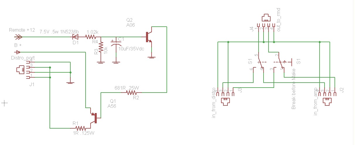
Matt, this may help. The remote circuit (left side) is pretty much identical to the circuit used in the amps to power the RMD.
The right had side of the picture is how I would do multiple switched inputs to the one RMD. You should use a "break before make" type switch, but in all likelihood, a generic switch will probably work fine.
Later,
Jason
The right had side of the picture is how I would do multiple switched inputs to the one RMD. You should use a "break before make" type switch, but in all likelihood, a generic switch will probably work fine.
Later,
Jason
M: M100, M44 for a custom amp project
Zx: Zx500, Zx450, Black Zx350
ZxTi: 4 Zx600Ti's, 1 Zx400Ti
Ti: 5 800.1's & 900.7 for a custom amp project. 1 1200.1, 1 1000.2
Tantrum: 2 1200.1's, 1 600.4, 1 500.2
XS: XS6600
Zx: Zx500, Zx450, Black Zx350
ZxTi: 4 Zx600Ti's, 1 Zx400Ti
Ti: 5 800.1's & 900.7 for a custom amp project. 1 1200.1, 1 1000.2
Tantrum: 2 1200.1's, 1 600.4, 1 500.2
XS: XS6600
Here´s a pic how that thing looks on the backside of the circuit board. So pretty much all i would have to do to resolve my problem is connecting a small wire from one of the screws to pin1 and pin3 and another wire from the ground section to pin2 and pin4??? Do i have to take some part´s out of it too?Jacampb2 wrote:Okay, pins 3 & 1 in the distro blocks port would need to be tied directly to B+ and 2 & 4 directly to ground to read actual battery voltage at the distro. If you want the display to turn on and off with the remote signal from the HU, you would need some additional components, and if not already there, a remote lead brought into the distro. I can help you with what you would need for the circuit, it would be a very simple setup with a transistor and a few resistors.
Later,
Jason
- Attachments
-
- DSC00813.jpg (89.44 KiB) Viewed 10487 times
Music is silver, PHOENIX is GOLD
I don't know if I would jump it at the board and possible send current back a way it was not intended. As he said this is nothing more then a volt-meter so why not just use a small wire off of + input to the dist block, and just ground the other side. You can use a relay to make a switched ground to turn off the display when either the deck or key is off. I know it doesn't use the RMD port like you wanted but this would not risk the internals of the block, and still read the voltage at the block. You could get a female jack and then just wire off of that.