Page 1 of 1
Lets play what missing from this picture
Posted: Tue May 19, 2009 4:45 pm
by GX3
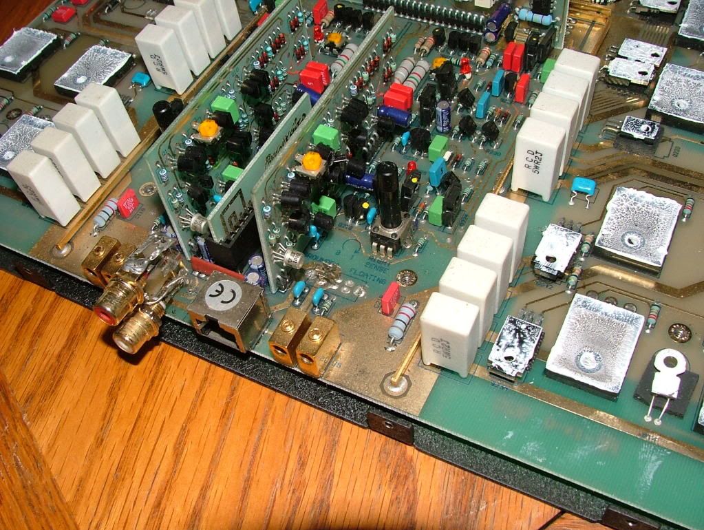
I have new RCAs to install but i need to know what has been removed/ripped from this board .....SW ??? but what kind SPST DPDT ?????
Posted: Tue May 19, 2009 4:55 pm
by bogart
Hey, is that the one you got from me...I didn't see that....knew it had issues but to have missed that...shameful
Posted: Tue May 19, 2009 4:56 pm
by 1moreamp
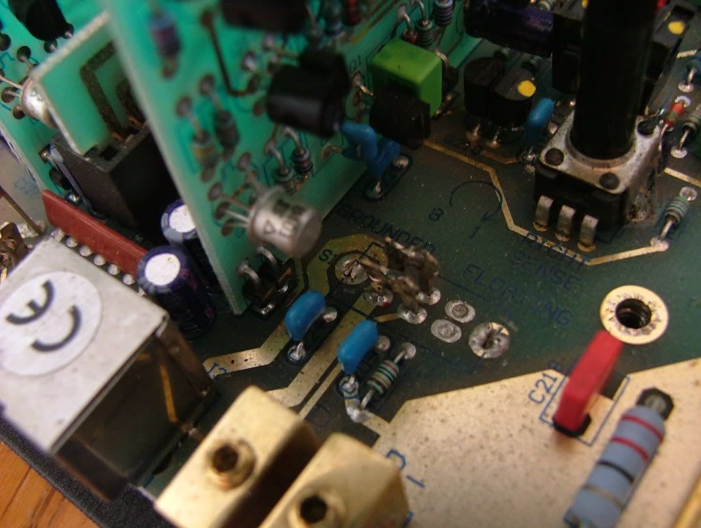
In V2 amps they did away with the switch , in your case the prior owner back one or two steps had decided to jumper the switch in the ground position, which is what PG did when they dropped the switch in V2... so except for coyote ugly its a workable solution.. I heard the switch caused issues with some owners so PG dropped it... and the RCAs would be nice to replace


i also replace the DC offset pot with a ten turn precision type, sort of removes all tediousness of making the adjustment to true zero offset...

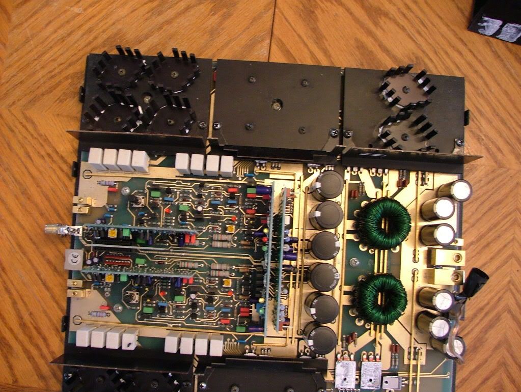
Also check the rear power supply board for bad solder joints on the big drop resistors, PG also did a fix on this issue as I recall, and you want to check it for big brown spots on the circuit board...Maybe post a pic, I know Eric has seen this before also...
Other then these very little things I say pretty nice so far....
Oh and check the two sense diodes on the front card bottom edge to see that they are still intact, if not the amp has been setup to run unlimited . I would put them back if they missing or disconnected.. but what do I know, eh?..
Posted: Tue May 19, 2009 5:33 pm
by mr tibbs
The top case??!!

Posted: Tue May 19, 2009 5:34 pm
by GX3
1moreamp wrote:In V2 amps they did away with the switch , in your case the prior owner back one or two steps had decided to jumper the switch in the ground position, which is what PG did when they dropped the switch in V2... so except for coyote ugly its a workable solution.. I heard the switch caused issues with some owners so PG dropped it... and the RCAs would be nice to replace
i also replace the DC offset pot with a ten turn precision type, sort of removes all tediousness of making the adjustment to true zero offset...
Also check the rear power supply board for bad solder joints on the big drop resistors, PG also did a fix on this issue as I recall, and you want to check it for big brown spots on the circuit board...Maybe post a pic, I know Eric has seen this before also...
Other then these very little things I say pretty nice so far....
Oh and check the two sense diodes on the front card bottom edge to see that they are still intact, if not the amp has been setup to run unlimited . I would put them back if they missing or disconnected..
but what do I know, eh?..
Just a little bit more then I

Ok thats a lot to take in so I'll take it step by step I can solder and desolder but might need help identifying the parts
Good news on the switch I'll just clean it up ( I was hopping it was the problem would have made this an easier fix)
As of right now I haven't powered her up ...Yes bogart this is the .3 I got from you ...... According to to Chris the one channel doesn't work properly maybe you can chime in here Chris to refresh my memory
I metered all the resistors under the sinks and all were good ... I need to get my other DMM back that has the diode setting on it before i can go on testing. The big drop resistors are the large white ceramic ones correct

i look ed and metered them and all was well
sense diodes??? on the cards to the left and right of the X-over or the one in the middle with the sat LEDs on it .. just looked on all 3 cards nothing looks to be removed or bypassed .....did notice C118 looks to be damaged look at the pics and just to left of the RCAs there is a small red cap with a chunk missing off the one corner
DC POTS the ones on the cards, main board or both???
brown spots ???? top or bottom
(only pic i have right now )
Posted: Tue May 19, 2009 5:36 pm
by Eric D
mr tibbs wrote:The top case??!!
No silly, the heatsinks are clearly what is missing...
Posted: Tue May 19, 2009 5:58 pm
by 1moreamp
sorry I forget I have this shit memorized
OK The diodes are located on the front power supply card in the middle of the amp. LOOK at the lower left hand corner for two little itty bitty diodes side by side. These get lift on one end or are just chopped out by really zealous folks. If they are there I suggest you leave them alone. these are the sense diodes that makes the amp knuckle over into low ohm mode that drops the output max to about 600 watts.

this is a 0.3 not a 0.5..DUH ! .. beware this mod can cause you serious failure rates if your not careful...I warned you...C
DC offset pots are those fugly yellow adjustments on each of the channel cards just behind the RCAs. I replace these with 10 turn precision pots by Bournes or Vishay pn Vis1240W < sorry I had the container handy >
Anyway the 10 turns make the adjust easy and not a feather touch issue...
The large sand blocks are the emitter resistors and yes they should all read the same, since most of your music will pass thru these to your speakers. These need a serious eye if a output went toasty on you...
The idle current at 12 vdc and no signal varies between 3 and 6 amperes, and you must measure the voltage across those sand blocks to verify proper bias of the output transistors. I use the end one close to the edge, my voltmeter probes just barely fit snugly underneath to measure across the two leads underneath but this is quick check, and the real measurement should be across a pair of these as the voltage drop equates to your bias settings. The higher the bias the hotter the amp runs even at idle so this adjustment is best made by PG or a tech with a distortion meter setup, unless Roland pages in here at anytime to gives a good ballpark figure of output bias setup.....I use a distortion meter, if the amp meets spec then VIOLA ! she be adjusted just fine....
Remember to re-grease all those tranny's just a touch will do before you button it up, and the bias setup needs the sink plates to be installed so a tracked and heat sensed bias setup is done correctly....ahhh whew !
If I missed anything someone kick the shit out of me and add it in
Posted: Tue May 19, 2009 8:56 pm
by fuzzysnuggleduck
Eric D wrote:mr tibbs wrote:The top case??!!
No silly, the heatsinks are clearly what is missing...
Haha, that was my first thought!
Posted: Tue May 19, 2009 9:03 pm
by mr tibbs
fuzzysnuggleduck wrote:Eric D wrote:mr tibbs wrote:The top case??!!
No silly, the heatsinks are clearly what is missing...
Haha, that was my first thought!
So, did I win??
Posted: Wed May 20, 2009 5:41 am
by bogart
I have no idea why a channel didn't work...saw signs of hack work on some transistors and hoped it was just the rca thing...the more I got into it the more I saw signs of someone being all over the board. Only had that amp on my bench for a few days and off she went. I though about trying to run her via the rddp to see but never did...
good luck gxs...