i have a zx475 that is having some front channel issues. rear plays fine. i see this is a common issue. i have a background in elec and the time to try and fix it. if i fail does Rodin still offer the flate rate repair service?
CraigsMax01 wrote:i have a zx475 that is having some front channel issues. rear plays fine. i see this is a common issue. i have a background in elec and the time to try and fix it. if i fail does Rodin still offer the flate rate repair service?
Pretty sure they are still doing it, I sent my 500.4 back in a few months ago, was $144 IIRC.
"Never underestimate the predictability of stupidity."
i believe my front left channel is dead. and i wanted to know what are the basics of troubleshooting an amp. i have a 30amp power supply and a nice voltmeter. i read something about measuring the current and voltage on each channel. i get less than .04 volts on each when powered up. rear channels both play fine. any help is great!
If the amp powers up, that is probably a sign the damage is not too great. Typically when a channel dies it shorts out and draws a ton of current from the power supply of the amplifier.
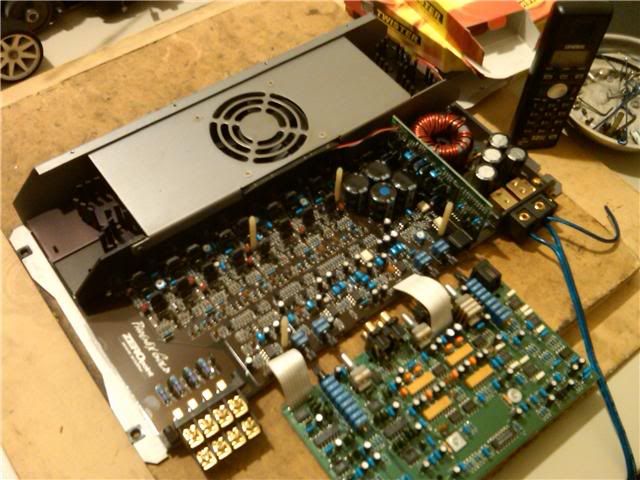
You are going to need to tear down the amp and get at the transistors for the front channels to test them.
i have i apart and ready to test, but i havent troubleshoot circuits like this since '99 LOL
all the leds that are visable come on except the 3 on top, but i see that is very common
how do i get to them and by what means do i test them. the heat sinks need to be taken off right?
thanks alot. i love my zx475 and want it fixed. and im handy enough to do it. but i never tried to fix an amp before. if i can fix copiers, i can fix an amp, i hope LOL
ok, i saw a few but did know if i had to take the heatsinks off first.
then i need to find the circuits for each channel and test the components.
transistors first?
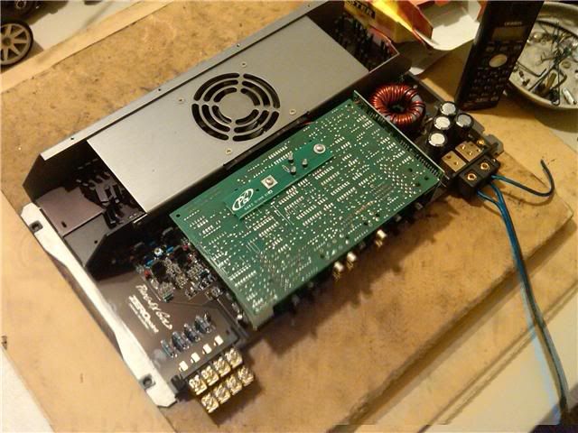
Once you take those screws out, then you have to take the fan cover off, then the transistors mounted to the heatsink front need to be unbolted, and then the screws removed from the heatsink plates, so you can pull them off of the board.
got the board off, i was halfway there last night but didnt want to mess it up.
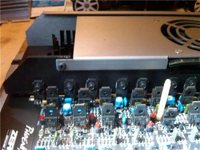
ok so remove the heatsinks carefully, with the bolts that are in the center of the individual heat sinks, bolts look like the nut driver type, and then the transistors are to be pried off lightly.
then i will be able to test with a meter, or will i need some specific tester?
got all the heatsinks screws out and the smaller section of the heat sink is off. but the half with a ton of screws on the side of the heat sink plate. how do i get these off? a very small wrench and time?
I would think you could sneak a socket on a wrench in there. They look to be spaced such that the wrench would go between the free standing transistors.
ok i will find something to get them off. and i googled how to check the diodes. but i geuss i need to find out how to check the transistors.
that will be tonights project.
i went to that site to. looks like they have everything to repair circuits!
also when i took the upper board assembly off the "X10" push button popped off, and two little copper pieces came out. i see the slide "IC" it came off of, but im not sure if im gonna know how they fit together and work.
FYI I had problems with my crossover board when I lost a channel on Zx475ti I gathered that bad crossover board were a common problem with this line of amps.
Dave
91 GMC Syclone - PG Ti 500.4AL, Boston Acoustic Z6, Exile XT10
12 Legacy - Stock