
Been a little depressing since I went outside and checked my caps. The ms2125 are leaking, but the 2500 doesn't seem to be leaking using the test that Eric and Cecil suggest.
I know this has been asked before and i've read the articles which are great BTW, but I guess i'm just asking to make sure what to get. My caps are leaking the set of 6 on each side, but not all of them are leaking, but I need to replace them since they haven't been replaced since what 93??
They are rated at 2200uf 16v in the amp right now. What should I buy to get more power or more life out of the caps. Please be specific and any websites or stores that might have them.
Thanks,
Kevin
MS2125 Leaking Caps Replacement
MS2125 Leaking Caps Replacement
Head Unit: Eclipse CD5000
Amp1: Ti 500.4
Amp2: MPS2500
Crossover: Audiocontrol 6xs
High/Mids: ID CD1-E v1 Horns
Midbass: IDQ 6.5 v2
Subs: IDQ 12 v1
EQ: PG EQ215-X
Amp1: Ti 500.4
Amp2: MPS2500
Crossover: Audiocontrol 6xs
High/Mids: ID CD1-E v1 Horns
Midbass: IDQ 6.5 v2
Subs: IDQ 12 v1
EQ: PG EQ215-X
http://phoenixphorum.com/zx350-caps-vt3 ... light=caps
Refer to that link for some ideas. I am not an amp repair expert, but 1moreamp talked about the 2200uf 16v froma Zx amp and suggest replacing them...which he mentions in the link there...see if that may help!
Refer to that link for some ideas. I am not an amp repair expert, but 1moreamp talked about the 2200uf 16v froma Zx amp and suggest replacing them...which he mentions in the link there...see if that may help!
The caps are perhaps the only weakness you will find with this series of amp, but its a common place issue with amps this old so please don't blame PG. The very fact they lasted this long is just amazing to say the least.
Replace them all on the 12 volt side with new are you will be good to go for another 15 years. I also ESR check the rail caps when I am doing this < the big blue ones on the amp side>. My 2125 had a broken one and NONE of the rest measured anywhere near spec or 10,000 uf. one was 8400uf and another was 4,450uf when tested.
These will be expensive, mine cost $48.00 from PG. Remember these are the weakness of ANY car amp made by anybody in the business. So here again these caps are like car battery's and I don't know anybody with a car battery over 5 years old.
Good Luck C
Here are two links that I found. Do any of these look like they will work?
http://www.partsexpress.com/pe/showdetl ... r=020-1066
http://www.digikey.com/scripts/DkSearch ... e=P6340-ND
Are those good ones or are there better caps out there?
Right off hand do you know the volts of the rail caps?
http://www.partsexpress.com/pe/showdetl ... r=020-1066
http://www.digikey.com/scripts/DkSearch ... e=P6340-ND
Are those good ones or are there better caps out there?
Right off hand do you know the volts of the rail caps?
Head Unit: Eclipse CD5000
Amp1: Ti 500.4
Amp2: MPS2500
Crossover: Audiocontrol 6xs
High/Mids: ID CD1-E v1 Horns
Midbass: IDQ 6.5 v2
Subs: IDQ 12 v1
EQ: PG EQ215-X
Amp1: Ti 500.4
Amp2: MPS2500
Crossover: Audiocontrol 6xs
High/Mids: ID CD1-E v1 Horns
Midbass: IDQ 6.5 v2
Subs: IDQ 12 v1
EQ: PG EQ215-X
soth wrote:Here are two links that I found. Do any of these look like they will work?
http://www.partsexpress.com/pe/showdetl ... r=020-1066
http://www.digikey.com/scripts/DkSearch ... e=P6340-ND
Are those good ones or are there better caps out there?
Right off hand do you know the volts of the rail caps?
Both of these are inferior parts I suggest you look for 105 degree temp ratings and low to ultra low ESR ratings. The caps your replacing were panasonic high grade 105 degree C rated caps.
The rail caps should be 10,000uf 50 volt for a 2125 although I have seen 40 volt one used in mine, I used 50 volt ones, for the 2500 they will be 15,000uf at 40 volt both should be 105 C rated. PG uses Nippon Chemi-con as replacements for the original CDE caps they used to use.
iv'e done one of my ms2125's, it's an easy job as long as you keep everything clean and let no slivers of wire entre your project like i did, i managed to take an output out through lack of concentration at the last minute. all is well now and glad i did the job 
Ti1 headunit (unique)
Outlaw in crate.
2x original shrouded ms2250's.
Route 66 in box + custom m100 to match.
Roadster 66 in flight case
Octane LE in box.
Reactor #186 in flight case.
Reactor EQ232
Ti400.2 AL
AX204A + EQ232 + ZPX2 + TBA set
ZCS6 component set
Tantrum+Titanium bass cubes
Ti12d Elite sub
DD5 + DD10 + 6 Ti blocks!
Would it not be good to have those 15,000uf on the 2125 also? (I am just thinking: more capacity=better??)1moreamp wrote:The rail caps should be 10,000uf 50 volt for a 2125 although I have seen 40 volt one used in mine, I used 50 volt ones, for the 2500 they will be 15,000uf at 40 volt both should be 105 C rated.
Selling your Ti9 mids? PM me, please..
I also need a DD10...
I also need a DD10...
-
brenzbmr@sb

- Booty Connoisseur
- Posts: 1611
- Joined: Wed Dec 06, 2006 9:49 pm
- Location: as ziggy marley said" on a beach in hawaii"
Ahh, OK. I'm just a computer(system/network) guy so you guys have been a big help here1moreamp wrote:soth wrote:Here are two links that I found. Do any of these look like they will work?
http://www.partsexpress.com/pe/showdetl ... r=020-1066
http://www.digikey.com/scripts/DkSearch ... e=P6340-ND
Are those good ones or are there better caps out there?
Right off hand do you know the volts of the rail caps?
Both of these are inferior parts I suggest you look for 105 degree temp ratings and low to ultra low ESR ratings. The caps your replacing were panasonic high grade 105 degree C rated caps.
The rail caps should be 10,000uf 50 volt for a 2125 although I have seen 40 volt one used in mine, I used 50 volt ones, for the 2500 they will be 15,000uf at 40 volt both should be 105 C rated. PG uses Nippon Chemi-con as replacements for the original CDE caps they used to use.
I defenitely want to use high quality parts in these amps
Any suggestions on what to practice on before attempting the removal/replacement of the caps on the actual amp? If not I can get a few of my friends to do since they have done a lot of that stuff before, but they would probably get annoyed because I would be picky as you know what when it comes to these amps
Head Unit: Eclipse CD5000
Amp1: Ti 500.4
Amp2: MPS2500
Crossover: Audiocontrol 6xs
High/Mids: ID CD1-E v1 Horns
Midbass: IDQ 6.5 v2
Subs: IDQ 12 v1
EQ: PG EQ215-X
Amp1: Ti 500.4
Amp2: MPS2500
Crossover: Audiocontrol 6xs
High/Mids: ID CD1-E v1 Horns
Midbass: IDQ 6.5 v2
Subs: IDQ 12 v1
EQ: PG EQ215-X
OK, I have a sequence I go through to even get the amp out of its case without damaging the sil-pads under the transistors.
IF you don't follow this you will have more troubles.
PG used Sil-pads and unless you have stock of these <like me> you must protect them upon removal of the circuit board. I also chamfer all the screw holes under the transistors as they thread pull under torque loading and I also remove all burrs and metal flakes in and around the mounting holes. < This is general clean up during and before reassembly >
I use a hot air rework station to preheat the transistors so they will release from the sink easily < about $107.00 on E-bay for a cheap one>.
I store all hardware in a special tray and later in a bag, especially the little torque washers.
Once apart and safely accounted for parts wise. I use a vari-temp solder station with the backup of a hot air rework station to apply heat from the bottom of the board ONLY.
I do not apply any pressure or stress to the cap being removed as it will pull out the circuit board thru-hole via's < PG uses double-sided circuit boards and where these caps mount the top side of the board is connected to the bottom side of the board. Great care must be exercised by you to prevent board damage. Solder wick and solder pault solder removal tools are advisable to remove excess solder from the joints before attempting to gently wiggle back and forth the cap leads to remove. First one lead, and then the other, back and forth till the cap gentle fails off the board into your hand.
I have over $500.00 worth of soldering tools just to do these sorts of jobs "safely, and correctly"And it takes more than 2 hours just to do a cap change and sometimes longer.
If your picky like you say and you follow the info above you will be pleased with your efforts. IF you rush, or don't practice skill and patience, your results will be heart breaking at minimum, with pulled and damaged via's, and the resulting repairs needed to restore contact on both sides of the board again.
Once you have done this few thousand times it becomes child's play and you can do it half asleep. The first time is always a screamer though....
If I sound dramatic well there is always a certain drama trying to do any work on other peoples property. I'm use to it and its a rush for me so I am at home. I hope this is also the way you feel after you have completed your work.
Best of luck, You have my procedures. Just temper it with patience and slow handed skill and you should be quite pleased withe the results.....C
Great advice Cecil. I do have the patience as I had to when I would paint/draw earlier in my life. I don't doubt I can do it, but it's the thought that it will be the 1st time though. In the end I know i'll be pleased especially if it all goes well. You get a feeling of accomplishment in something like that
Thanks for all the advice.
Kevin
Thanks for all the advice.
Kevin
Head Unit: Eclipse CD5000
Amp1: Ti 500.4
Amp2: MPS2500
Crossover: Audiocontrol 6xs
High/Mids: ID CD1-E v1 Horns
Midbass: IDQ 6.5 v2
Subs: IDQ 12 v1
EQ: PG EQ215-X
Amp1: Ti 500.4
Amp2: MPS2500
Crossover: Audiocontrol 6xs
High/Mids: ID CD1-E v1 Horns
Midbass: IDQ 6.5 v2
Subs: IDQ 12 v1
EQ: PG EQ215-X
Hey guys, just a quick question about the size/length of the caps.
Link to panasonic that i'm going to order.
http://search.digikey.com/scripts/DkSea ... =P10266-ND
Digi-Key part #: P10266-ND
Panasonic# EEUFC1C822
It's 8200uf, 105c, 16v, 18 diamater and 35.5 tall.
The 6800uf is 105c, 16v, 16 Diamater and 31.5 tall
I'm thinking the 35.5 is too tall, but would the 16 diamater on the 6800 be too small?
Again, thanks to all
PS: Usually i'm the one answering all the questions (computer related) on forums and i'm asking all the questions here
Only way to learn though so try not to get too mad
Kevin
Head Unit: Eclipse CD5000
Amp1: Ti 500.4
Amp2: MPS2500
Crossover: Audiocontrol 6xs
High/Mids: ID CD1-E v1 Horns
Midbass: IDQ 6.5 v2
Subs: IDQ 12 v1
EQ: PG EQ215-X
Amp1: Ti 500.4
Amp2: MPS2500
Crossover: Audiocontrol 6xs
High/Mids: ID CD1-E v1 Horns
Midbass: IDQ 6.5 v2
Subs: IDQ 12 v1
EQ: PG EQ215-X
At least your open minded, thats a important survival trait in the modern world.
I suggest you limit you height to 35 MM in the lager 10 k caps, and 35 mm in the smaller 12 volt side caps. Case considerations being what they are you will want to put the cover back on tine amp when your done
Use a small steel ruler and do the metric conversion. Most sellers use Metric in case dimensions.
-
nico boom
- Deus ex MS

- Posts: 2089
- Joined: Fri Jan 05, 2007 1:40 pm
- Location: the land of wooden shoes
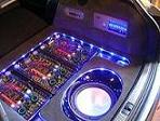
Just finished one for a friend; this is what it lookes like while doing it.
I only changed the input filtering caps; changing the blue ones as well is even better, considering the work to get the board out of the sink.
GOOD LUCK; you already had the best advice you can possibly get from the people who know best.
nico
I only changed the input filtering caps; changing the blue ones as well is even better, considering the work to get the board out of the sink.
GOOD LUCK; you already had the best advice you can possibly get from the people who know best.
nico
- Attachments
-
- DSC01620.JPG (199.46 KiB) Viewed 10273 times
-
- DSC01616.JPG (202.57 KiB) Viewed 10273 times
-
- DSC01613.JPG (193.03 KiB) Viewed 10273 times
-
- DSC01612.JPG (202.51 KiB) Viewed 10273 times
-
nico boom
- Deus ex MS
- Posts: 2089
- Joined: Fri Jan 05, 2007 1:40 pm
- Location: the land of wooden shoes
Thanks Cecil; coming from you, that's a real compliment..
Send me the amps that you can't repair, and I'll just repair them for you in your European lab.. ....
....
[I can easily make this joke, as no amp will come my way; you just repair them ALL..]
One thing I do different than before; after the holes in the board are completely clean, and the new cap-conductors slide through easily, I fit each cap on the board, and cut the excess "wire-length" to 2mm. sticking out of the board BEFORE SOLDERING.
This way, the solder-joint forms a beautiful connection that does not need any clipping [no stress on the board and connection], and the joint is just beautiful.
Also I have no worries that the joint will be to high, causing it to press to the isolation-sheet, and short-circuit on the heatsink.
IMO a better way to do this job.
My wife holds down each cap, pressing it perfect to the board,while I do the soldering.. good team-building!
We continue the pressing down afterwards sometimes as well
nico
Send me the amps that you can't repair, and I'll just repair them for you in your European lab..
[I can easily make this joke, as no amp will come my way; you just repair them ALL..]
One thing I do different than before; after the holes in the board are completely clean, and the new cap-conductors slide through easily, I fit each cap on the board, and cut the excess "wire-length" to 2mm. sticking out of the board BEFORE SOLDERING.
This way, the solder-joint forms a beautiful connection that does not need any clipping [no stress on the board and connection], and the joint is just beautiful.
Also I have no worries that the joint will be to high, causing it to press to the isolation-sheet, and short-circuit on the heatsink.
IMO a better way to do this job.
My wife holds down each cap, pressing it perfect to the board,while I do the soldering.. good team-building!
We continue the pressing down afterwards sometimes as well
nico
- Attachments
-
- condensators soldering.JPG (118.23 KiB) Viewed 10257 times
Awesome! I can't wait to get started on replacing mine. Going to go out and practice with the stuff here in a few minutes on something Don't know what yet, but i'm going to try and get the hang of it. Doesn't look too difficult now with all your guys help.
Now to just find some of that wicker stick or whatever Eric uses to clean up the solder from the board when it's heated back up.
Wish me luck!
Kevin
Now to just find some of that wicker stick or whatever Eric uses to clean up the solder from the board when it's heated back up.
Wish me luck!
Kevin
Head Unit: Eclipse CD5000
Amp1: Ti 500.4
Amp2: MPS2500
Crossover: Audiocontrol 6xs
High/Mids: ID CD1-E v1 Horns
Midbass: IDQ 6.5 v2
Subs: IDQ 12 v1
EQ: PG EQ215-X
Amp1: Ti 500.4
Amp2: MPS2500
Crossover: Audiocontrol 6xs
High/Mids: ID CD1-E v1 Horns
Midbass: IDQ 6.5 v2
Subs: IDQ 12 v1
EQ: PG EQ215-X
solder wick, much better than a solder sucker. i was a die hard fan of the solder sucker till i gave the solder wick a go
Ti1 headunit (unique)
Outlaw in crate.
2x original shrouded ms2250's.
Route 66 in box + custom m100 to match.
Roadster 66 in flight case
Octane LE in box.
Reactor #186 in flight case.
Reactor EQ232
Ti400.2 AL
AX204A + EQ232 + ZPX2 + TBA set
ZCS6 component set
Tantrum+Titanium bass cubes
Ti12d Elite sub
DD5 + DD10 + 6 Ti blocks!
Outlaw in crate.
2x original shrouded ms2250's.
Route 66 in box + custom m100 to match.
Roadster 66 in flight case
Octane LE in box.
Reactor #186 in flight case.
Reactor EQ232
Ti400.2 AL
AX204A + EQ232 + ZPX2 + TBA set
ZCS6 component set
Tantrum+Titanium bass cubes
Ti12d Elite sub
DD5 + DD10 + 6 Ti blocks!
BEWARE ! applying constant pressure will load the terminals with tension, can cause the connections inside the cap to pull against the bottom seal. this could conceivably cause leakage by itself. If your looking for solid contact use RTV, just a dab on the bottom will seal the cap to the board and if properly applied it will protect the gold traces from any eventual leakage that might occur.
DAMN now i gotta kill all of you I just spilled my guts of another secret
Seriously don't tension load the caps to the board with pressure, it removes all thermal expansion ability from the assembly. Caps leak do to the seals failing mostly due to heat and chemical reactions to the wire conductors, shock and vibration. Some higher grade caps are sealed with epoxy on the bottom and appear to have been sealed for life this way. but you don't want to ask what these caps cost
No electronics assembly I have ever seen has the caps pressure loaded, in fact most have long leads with elevated position above the board. Just look at the smaller caps on the amp.... C
-
nico boom
- Deus ex MS
- Posts: 2089
- Joined: Fri Jan 05, 2007 1:40 pm
- Location: the land of wooden shoes
I hear you Cecil ; the pressing down on the board was much more gentle than the pressing afterwards..
She just holds them in place, so that I have both hands free.
No worry's here, and thanks for the secret tip; I used it in the 90's, when people used to screw down their amps on a badly-build subwoofer-enclosure, resulting in loose caps, and other components
The challenge is, to put just enough under each cap, so that it does the job, without any excess coming from under it, isn't it.
For the "abusers" I also just glued the caps together, cause they would again be screwing it to that cabinet afterwards....
SOTH;try solder-wick; you'll never use any other way to get rid of the old solder again!
GOOD LUCK. [and have fun, it's a nice job to do].
nico