Page 1 of 2
M44 Cap Replacement
Posted: Thu Feb 14, 2008 5:25 am
by dwnrodeo
I just picked up this little item yesterday and did the paper test for the caps and as I suspected they are leaking. My question is, what is the maximum height for cap that I can use? I am looking at this cap right now (Link)
http://www.mouser.com/Search/ProductDet ... bDiA%3d%3d Would this model be an acceptable replacement? I see that it is 35.5 mm tall and I've heard that there might be clearance issues with that height. Also (Eric or Cecil) would you recommend I replace anything else while I'm at it?
Sorry for all of the questions, and as always thanks for any help.
Posted: Thu Feb 14, 2008 5:37 am
by Eric D
I am sure 35.5 is as high as you can go. The 5,600uF caps I tell everyone to get were chosen because they cleared in all my M amps and in my ZX amps as well. There is a 10,000uF cap I use in Reactors (based on the ZX line) which fit because the Reactor has about 0.25” more clearance due to its shroud.
You may want to replace some resistors on that amp, or at least move them away from the board a bit if you can. The big ones near the large caps are the ones of concern.
Posted: Thu Feb 14, 2008 5:55 am
by dwnrodeo
I'm assuming you mean the 4 resistors shown in the picture below right? Are those 1000 Mohm resistors?
Posted: Thu Feb 14, 2008 6:03 am
by Eric D
Sorry, no I was talking about the ones to the bottom right of the big blue caps.
Posted: Thu Feb 14, 2008 6:27 am
by dwnrodeo
Thanks, I'll look into replacing those as well.
Posted: Thu Feb 14, 2008 7:32 am
by marko
i've noticed those resistoes can get very hot and unbarable to touch for more than a few seconds, is this anything to worry about? maybe upgrade to higher wattage resisitors?
Posted: Thu Feb 14, 2008 8:10 am
by 1moreamp
marko wrote:i've noticed those resistoes can get very hot and unbarable to touch for more than a few seconds, is this anything to worry about? maybe upgrade to higher wattage resisitors?
Morning Marko, Yes upgraded wattage devices are AOK here to increase lifespan and the heat will have a larger surface area to be dissipated with higher wattage devices.....and you can mount them further off the board thus reducing the amount of heat the board has to endure...C
Posted: Thu Feb 14, 2008 8:42 am
by marko
1moreamp wrote:marko wrote:i've noticed those resistoes can get very hot and unbarable to touch for more than a few seconds, is this anything to worry about? maybe upgrade to higher wattage resisitors?
Morning Marko, Yes upgraded wattage devices are AOK here to increase lifespan and the heat will have a larger surface area to be dissipated with higher wattage devices.....and you can mount them further off the board thus reducing the amount of heat the board has to endure...C
great, i thought so, i have 2 ms2250's and the one in my car has larger resistors fitted but the other doesn't and these get too hot to touch! also noticed this in my m100 too...
Posted: Thu Feb 14, 2008 11:30 am
by 1moreamp
marko wrote:1moreamp wrote:marko wrote:i've noticed those resistoes can get very hot and unbarable to touch for more than a few seconds, is this anything to worry about? maybe upgrade to higher wattage resisitors?
Morning Marko, Yes upgraded wattage devices are AOK here to increase lifespan and the heat will have a larger surface area to be dissipated with higher wattage devices.....and you can mount them further off the board thus reducing the amount of heat the board has to endure...C
great, i thought so, i have 2 ms2250's and the one in my car has larger resistors fitted but the other doesn't and these get too hot to touch! also noticed this in my m100 too...
Yeah, its pretty normal for these to get hot to the touch. If you measure across the resistor with a voltmeter you will see why these get hot.
You will see that they have very large voltage drops across them. They drop the high voltage rails in front of the simple zener regulators for the 15 volt rails, and provide current limits also.
PG designed them to do this and its all fairly normal stuff. And as long as they still read there rating in ohms then they are probably fine. The only issue I ever see with these is that the excessive heat transfers to the leads and causes the solder connections to break down with time and use.
Attempting to resolder these is almost impossible, as the leads have become heavily oxidized from the heat and won't take solder any longer unless you can pull the resistor and remove the oxide with chemical etch or scotch brite by polishing the leads.
Then reinstall now that the solder will stick to the leads again. This is why Doc replaces them with new. The cleaning process is a pain, and new ones just drop in, and take solder.
Increasing the wattage does not hurt anything and will give the heat a larger area to be displaced across and possibly lowering the overall temperature a bit, and maybe aiding in keep the solder connection solid for a longer time.
Another possible addition to this issue is to use "Silver Solder" to the connection. Silver solder has a much higher melt point and will hold up to heat much better over time. The down side is the extra heat required to get the solder to flow and bond. The un-monitored use of heat at this level can damage the board I.E. lift traces by causing the copper cladding to debond.
Most people are unaware that the copper on all PCB's is bonded on in layers in a hot press that technically Laminates a copper layer to the fiberglass board stock under 20,000 + pound of force with temp in the 400+ degree C range or higher. Once these temps are reached again without the pressure applied the copper can lift right off the fiberglass panel leaving you with a hole and no conductor material to make the circuit...I.E. the bonding agent melts and the copper peels right off...Then you have damaged the board permanently.
Hope this helps in some way...C
Posted: Fri Feb 15, 2008 5:02 am
by dwnrodeo
By the way, are those two resistors 91 ohm, 1/4 watt? Just wanted to double check. Also, I'm looking for a replacement for one set of the RCA inputs. Apparantly one of the front inputs has the inside connector pushed in. And I'm looking for some replacement gold speaker screws, as you can see from the pics the previous owner replaced with regular black screws.
Posted: Fri Feb 15, 2008 11:24 am
by 1moreamp
(1 ohm 3 watt is there 91 ohm 5 watt is most likely replacement Wirewound white sand block body is ok...C
Posted: Fri Feb 15, 2008 11:58 am
by dwnrodeo
Thanks for your help (C and Doc)! All parts are ordered and on their way.
Still looking for speaker screws and rca inputs. Any suggestions? Do you think PG would have some rca inputs still available for this amp?
Posted: Fri Feb 15, 2008 1:10 pm
by 1moreamp
JandRelectronics on ebay has RCAs from SoundStream amps the USA series these are the same RCA except foi the metal spine in the center backside and thats a swappable piece. Jusy ask Jaime for USA RCAs..
As for gold screws there are also on e-bay just look them up.
Or call Phil at PG I am sure he has these also....C
Re:
Posted: Sat Jul 07, 2012 10:11 am
by JayGold
dwnrodeo wrote: All parts are ordered and on their way.
Just to verify, are the (2) resistors below and right to the large blue caps recommended replacement values?
91K ohm, 5 watt
Re: M44 Cap Replacement
Posted: Sun Jul 08, 2012 1:24 am
by zeropoint0.5
http://be.mouser.com/ProductDetail/Xico ... DXhZ0g0%3d
check this link for the 91 ohms, 5W resistors.....for the M44
Re: M44 Cap Replacement
Posted: Sun Jul 08, 2012 8:58 am
by JayGold
Thanks man, I wanted to verify that those specs were still recommended replacements.
Re: M44 Cap Replacement
Posted: Sun Jul 08, 2012 10:26 am
by zeropoint0.5
M50 ---- two resistors of 330 ohms....
M100--- four resistors of 160 ohms....
zpa0.5--two resistors of 330 ohms....(R35/R36)
other amps i don't know the values.....
i replace them all with a 5W model and 1/2inch to 3/4inch away from the board.....
make sure they don't "touch" a little cap or something.
Re: M44 Cap Replacement
Posted: Sun Jul 08, 2012 2:43 pm
by JayGold
zeropoint0.5 wrote:M50 ---- two resistors of 330 ohms....
M100--- four resistors of 160 ohms....
zpa0.5--two resistors of 330 ohms....(R35/R36)
other amps i don't know the values.....
i replace them all with a 5W model and 1/2inch to 3/4inch away from the board.....
make sure they don't "touch" a little cap or something.
Good info there, I own all but the 0.5...thanks!
Here's another one for ya (M44 side of RT66), what is the value on the small melted blue shrinked cap below the hot resistors?
Re: M44 Cap Replacement
Posted: Sun Jul 08, 2012 11:27 pm
by zeropoint0.5
JayGold wrote:zeropoint0.5 wrote:M50 ---- two resistors of 330 ohms....
M100--- four resistors of 160 ohms....
zpa0.5--two resistors of 330 ohms....(R35/R36)
other amps i don't know the values.....
i replace them all with a 5W model and 1/2inch to 3/4inch away from the board.....
make sure they don't "touch" a little cap or something.
Good info there, I own all but the 0.5...thanks!
Here's another one for ya (M44 side of RT66), what is the value on the small melted blue shrinked cap below the hot resistors?
i should open an amp to be sure, but i thought, exactly the same as the one just next to it !!
i tried to upload a pic, but the file was to big !!
Re: M44 Cap Replacement
Posted: Mon Jul 09, 2012 5:32 am
by JayGold
zeropoint0.5 wrote:
i should open an amp to be sure, but i thought, exactly the same as the one just next to it !!
i tried to upload a pic, but the file was to big !!
It may be the same (too melted to tell), I just want to verify before I order some up.
Re: M44 Cap Replacement
Posted: Mon Jul 09, 2012 9:11 am
by zeropoint0.5
JayGold wrote:zeropoint0.5 wrote:
i should open an amp to be sure, but i thought, exactly the same as the one just next to it !!
i tried to upload a pic, but the file was to big !!
It may be the same (too melted to tell), I just want to verify before I order some up.
i will open an m44, try to take a pic as good as possible......
but uploading here is always a bitch when the files are too big.......
if you leave an emailadress here or pm me , i'll send you the pics..... i have trouble
of resizing them.......
i just took a look.... it is 47mF, 16V, 85°C, like the one just next too it....
if i can i upload a pic.
Re: M44 Cap Replacement
Posted: Mon Jul 09, 2012 11:56 pm
by JayGold
zeropoint0.5 wrote:JayGold wrote:zeropoint0.5 wrote:
i should open an amp to be sure, but i thought, exactly the same as the one just next to it !!
i tried to upload a pic, but the file was to big !!
It may be the same (too melted to tell), I just want to verify before I order some up.
i will open an m44, try to take a pic as good as possible......
but uploading here is always a bitch when the files are too big.......
if you leave an emailadress here or pm me , i'll send you the pics..... i have trouble
of resizing them.......
i just took a look.... it is 47mF, 16V, 85°C, like the one just next too it....
if i can i upload a pic.
That's cool bro, no need to take pics. I appreciate the info. Thanks!
Re: M44 Cap Replacement
Posted: Tue Jul 10, 2012 12:42 am
by zeropoint0.5
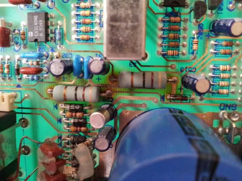
pics succesfully resized. the green wirewound resistors are not the ones from the mouser link.....
they were the only ones available at farnell(european newark) at the moment..... result stays the same.....
no regrets about this resistor replacement.... it is much much more reliable.....if you don't do it, the board will
discolor just as the little caps around them ......If i would buy tomorrow another M44 i would directly do the same !!
Re: M44 Cap Replacement
Posted: Tue Jul 10, 2012 10:09 am
by JayGold
zeropoint0.5 wrote:pics succesfully resized. the green wirewound resistors are not the ones from the mouser link.....
they were the only ones available at farnell(european newark) at the moment..... result stays the same.....
no regrets about this resistor replacement.... it is much much more reliable.....if you don't do it, the board will
discolor just as the little caps around them ......If i would buy tomorrow another M44 i would directly do the same !!
Those are great pics, thanks for uploading.
I'm going to replace them with the Mouser link resistors.
I see you have a half melted small blue capacitor too...what's your take on the smaller ones, are they just ALL prone to heat no matter location on the board?
Re: M44 Cap Replacement
Posted: Tue Jul 10, 2012 12:28 pm
by zeropoint0.5
JayGold wrote:zeropoint0.5 wrote:pics succesfully resized. the green wirewound resistors are not the ones from the mouser link.....
they were the only ones available at farnell(european newark) at the moment..... result stays the same.....
no regrets about this resistor replacement.... it is much much more reliable.....if you don't do it, the board will
discolor just as the little caps around them ......If i would buy tomorrow another M44 i would directly do the same !!
Those are great pics, thanks for uploading.
I'm going to replace them with the Mouser link resistors.
I see you have a half melted small blue capacitor too...what's your take on the smaller ones, are they just ALL prone to heat no matter location on the board?
yeah, at the time i hadn't yet replaced it.... those pics are from some time ago. I didn't had the mouser resistors then.
if you replace them, put them at the same high i did.... it is really not to much...
what do you mean with
"what's your take on the smaller ones, are they just ALL prone to heat no matter location on the board? "
are you talking about resistors or caps ??