Page 1 of 1

Why do you never have the right mosfet...

Posted: Tue May 27, 2008 6:12 am
by Jacampb2
Well, I have been working on my Tantrum 1200.1 I bought from Wakeup. All 12 power supply FETs were blown when I opened it up. There was also some significant damage to the traces on the board. I had never seen this much damage in a PG amp. I assumed that the PO that wakeup bought it from hooked up power backwards...

I replaced the power supply FETs and all of their SMD gate resistors (what a PITA), repaired the burned traces and put power back to it. At idle it was drawing lots of current and getting really F-ing hot! I couldn't leave power on it for more than a few seconds as the toroids and power supply FETs hit 130° F in moments. I finally found what I hope is the final problem. Two of the big ass output FETs are shorted drain to source. I pulled them off the board and the amp powers up fine. Of course I don't have any of the correct replacements in my collection, so I had to order some...

After I found that, I decided to repair the 600.4 I had awaiting some lovin'. The 600.4 had one non working channel, when I got it, I opened it up and found a blown pnp/npn complimentary pair that was blown. I swapped them out along with their gate resistor. On a whim, I decided to check it's output FETs, just in case that is what took out the complimentary pair. Sure enough, output FET is blown. This one is small enough I thought there was a chance I had a replacement, but the closest I had was likely not a fast enough FET to put in it's place, so I had to order those as well!

Anyhow, I ordered extras of each, but I am sure the next one I run into won't be a close enough match either. It sure would be nice to have an actual electronics supplier nearby and not have to mail order every gawd damned thing!

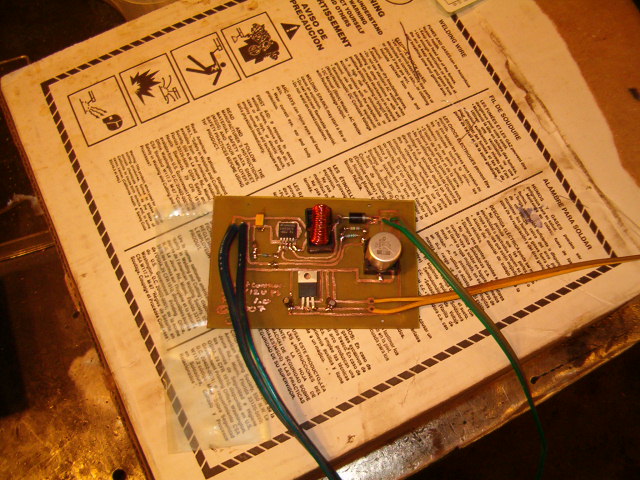
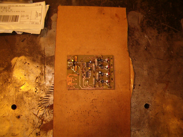
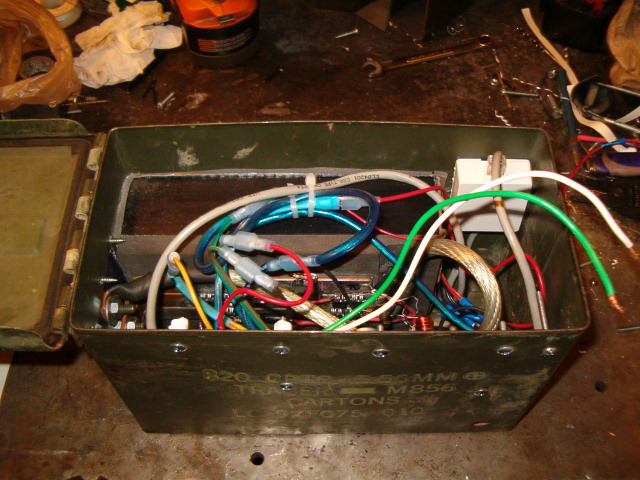
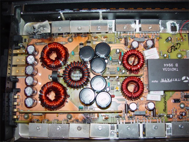
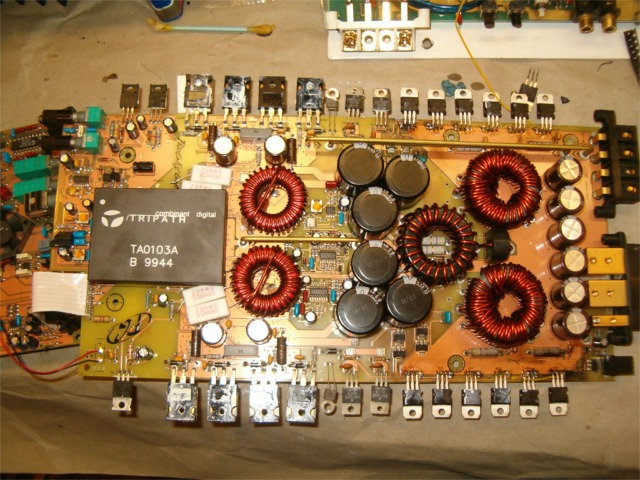
Here are some pics of the tantrum. The first one is from Wakeup before I bought the amp. The second shows the PS FETs all replaced. It isn't the most elegant repair, but there is only so much you can do with the burned traces...

Image

Image

Later,
Jason

Re: Why do you never have the right mosfet...

Posted: Tue May 27, 2008 7:31 am
by stipud
Jacampb2 wrote:It isn't the most elegant repair, but there is only so much you can do with the burned traces...
Hey, if it works, who cares? :lol:

Damn that is some nasty warping on that heatsink.

Posted: Tue May 27, 2008 8:08 am
by Jacampb2
The heat sink did not sutain any damage, just the .125" aluminum clamp bars. Those will be easy enough to knock out new ones. I am using silicone-kapton heat transfer tape this time, instead of HS compound, mainly because I have it, but the stuff is awesome, A perfect dielectric, thermally conductive film, and no mess. The downfall is it is expensive, About $15 for 5 foot.

I had it around from a project last year, I built a HUGE H Bridge for controlling a off road winch. It is capable of switching about 600Adc, I used IRF HexFets in D2Pak7 configuration, and the mounting tab is also the drain. I cooled them all with one monster peltier, and since the tab is part of the circuit, they had to be isolated from the conductive sink. It is pretty freaking wild.

Later,
Jason

Posted: Tue May 27, 2008 8:12 am
by stipud
Damn that sounds beefy. Got any pics?

Posted: Tue May 27, 2008 8:33 am
by Jacampb2
Here ya go:

Image

30VDC switch mode PS, this is required to get the gate voltage up high enough above ground for full enhancement. The 30Vdc is also regulated back down to 12Vdc on the same board, the 12Vdc powers other stuff in the circuit.

Image

This is the gate driver board, switch debounce, and driver logic. Lots of SMD parts on this one, I ordered them by mistake, my first ever experience with them, and trust me, it isn't fun!

Image

These are the HexFets all soldered down to 1"x.25" solid copper buss bars. This was really difficult, and isn't pretty, had to torch solder the SOBs down, the copper buss is just too thick to heat any other way...

Image

Image

And here is the finished product, the big black thing is the peltier, it gets cold enough that the buss gets frosty at idle, I measured the temp via IR at -17° F. I have tested it, and it does work, but I have not tested it "hard" in off road conditions. This was my first electronics project that was from the ground up. I had lots and lots of help from a EE I met on another bulletin board.

Later,
Jason

Posted: Tue May 27, 2008 9:21 am
by stipud
Thanks for sharing that.

I must say it looks pretty bad ass in the old ammo box :lol:

Posted: Tue May 27, 2008 9:32 am
by Bfowler
wow, thats a hell of a project!

Posted: Tue May 27, 2008 9:37 am
by Jacampb2
I have to say, it would be bad ass to design a monster amp with these Fets. It has been a while since I looked at the datasheet, but I know that they are rated at 429 Adc each, package limit of 160 Adc though. They are probably a bit to slow for an amplifier though...

I hope I never have the bridge shoot through, it will likely be a very nasty fire!

Later,
Jason

Posted: Wed Jun 11, 2008 6:44 am
by Jacampb2
Well, I got around to testing the T1200.1 the other day, put it in the truck in direct replacement of my known good T1200.1. It had some output, but garbled and shitty sounding. I pulled it back out, figured there were more problems. After checking the rail voltage on the bench, again, BTW (+/-54VDC, 108VDC referenced to the negative rail), and finding no issues, I hooked it up to my shop stereo and the thing played flawlessly with the bottom cover off, but every time I wiggled the xover card, it went all freaky sounding again.

I took it back to the bench and found that the input RCA board connections were loose. I de-soldered, re-soldered and put it back together and it sounds great. Thank god the Tripath chip is okay!

Which brings me to my next question. Do any of you think I would be crazy to rewind the toroids to get her close to +/- 70Vdc rails? The Ta0103a tripath chip can handle a rail voltage of a maximum of +/-85Vdc. 70 volt rails would probably push it close to the 2KW range at 2 ohms. Or, I have sourced some Ta0105a chips, which are pin compatible with the 0103, but their normal rail voltage is +/-170Vdc. It would take some substantial redesign (likely a whole new amplifier), but the 105 is capable of 5Kw at those rail voltages... I probably won't :twisted: but it is fun to think about...

Later,
Jason

Posted: Wed Jun 11, 2008 7:01 am
by stipud
I like where you're goin :lol:

Heck, if you don't have anything better to do with the amp, you might as well make it into a frankenstein ;)

Posted: Wed Jun 11, 2008 7:28 am
by Jacampb2
Well, I had intended to run my 4 CV Strokers with the pair when the bronco is done, however, I just bought the 3 800.1 boards tristan had for sale, and I am going to find a 4th and drive the CV's with those. I can sell the one cherry t1200.1 and keep the damaged one and do whatever I want with it... Another option would be the ta0104a chipset, it will do 3Kw at roughly +/-100Vdc. Probably a better fit to the tantrum amplifier as a starting point. It would still take significant power supply and output redesign, but it would be a better fit. The 104 is pretty tough to find though, about as hard as finding the 103...

Later,
Jason

Posted: Wed Jun 11, 2008 7:40 am
by BlackWaterOp.
I love the ammo case. There is/was definitely alot of damage done to that Tantrum, at least the Tri-chip was still good.