Page 1 of 1
Replacing caps and resistors... I screwed up
Posted: Fri Nov 28, 2008 5:26 pm
by denisl
Hi... It's been a while since I was asking advise how to fix my M44 and M50, well I finally got around to it and am now worried.
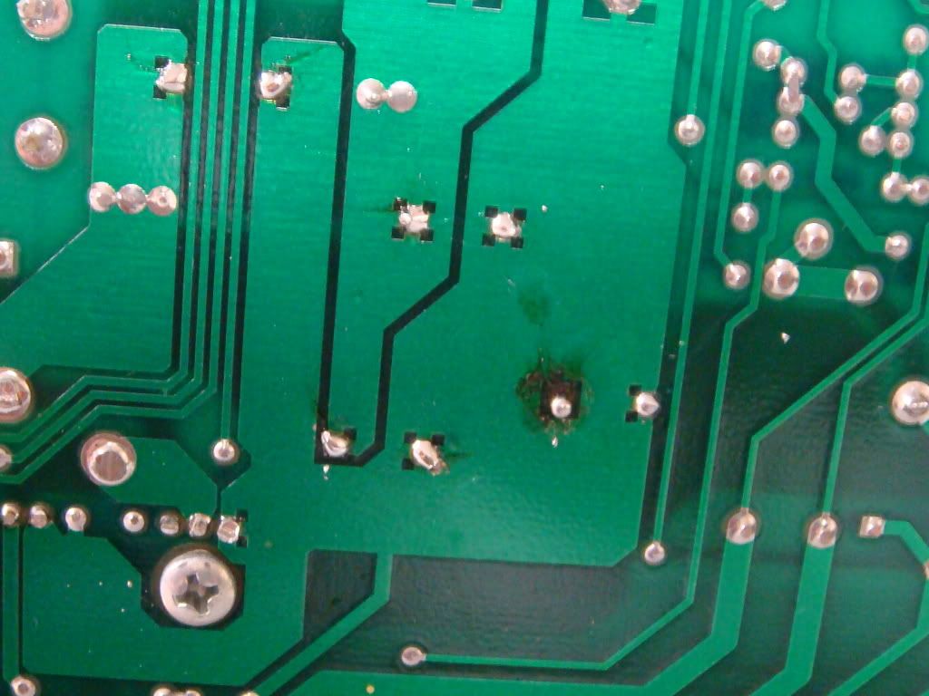
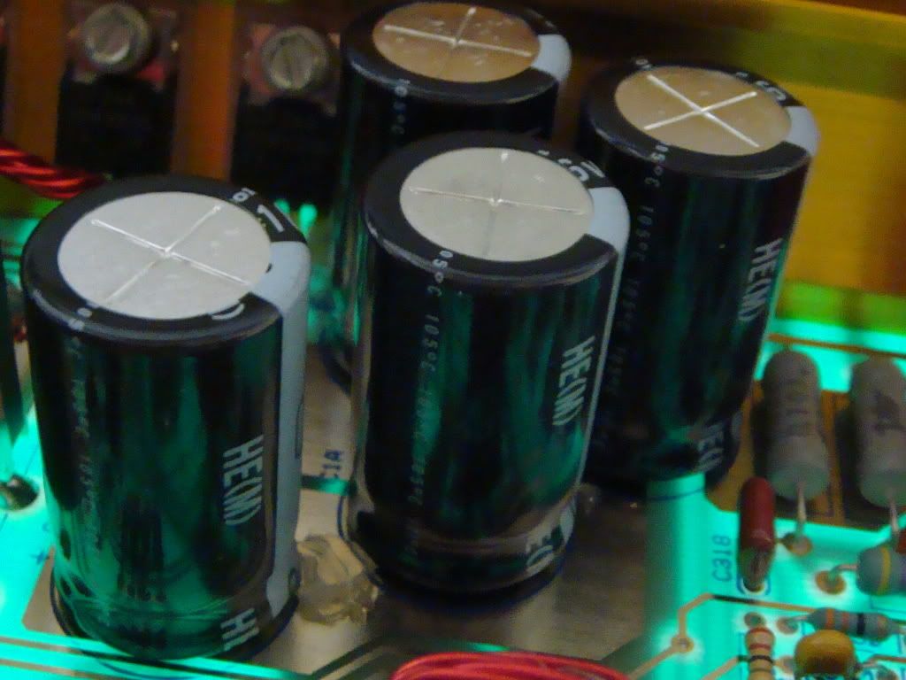
I replaced all the power caps and big DC caps as well as those resistors which looked like they got pretty hot. Of the 30 or so solder connections I made on the back of the board two of them look like absolute shit and I don't know what to do. I think I damaged the board.
The picture is embarassing.... Any advise to save my amps?
Posted: Fri Nov 28, 2008 5:28 pm
by Wakeup
Well unfortunately however embassing the picture may be, the picture might help us(not me...I dont know how to fix them...but others might) to be able to advise you how to fix it.
Posted: Fri Nov 28, 2008 5:32 pm
by denisl
sorry - pic is up.
Posted: Fri Nov 28, 2008 6:49 pm
by GX3
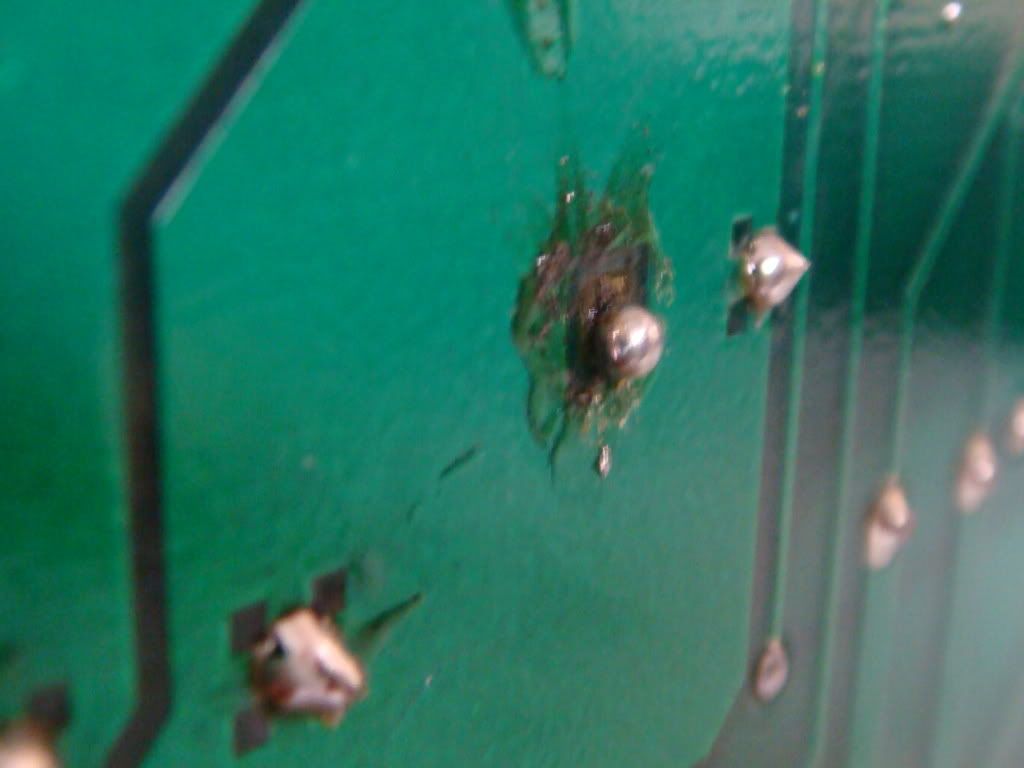
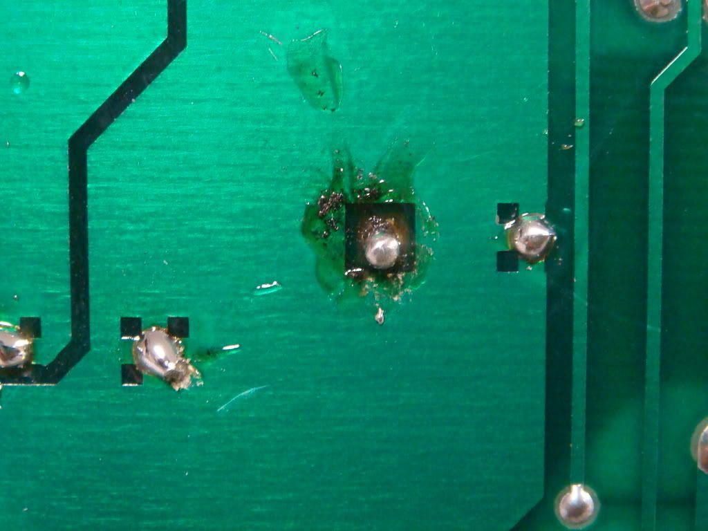
In the pic just above the solder is that the PC board you can see??? is the joint solid or is it lose? the clear yellowish fluid is the flux from the solder not much to worry about there it can be cleaned off. Is there any way you can take a picture on a bit of an angle so we can see the side of the joint
Posted: Fri Nov 28, 2008 7:15 pm
by yesterdaysyouth
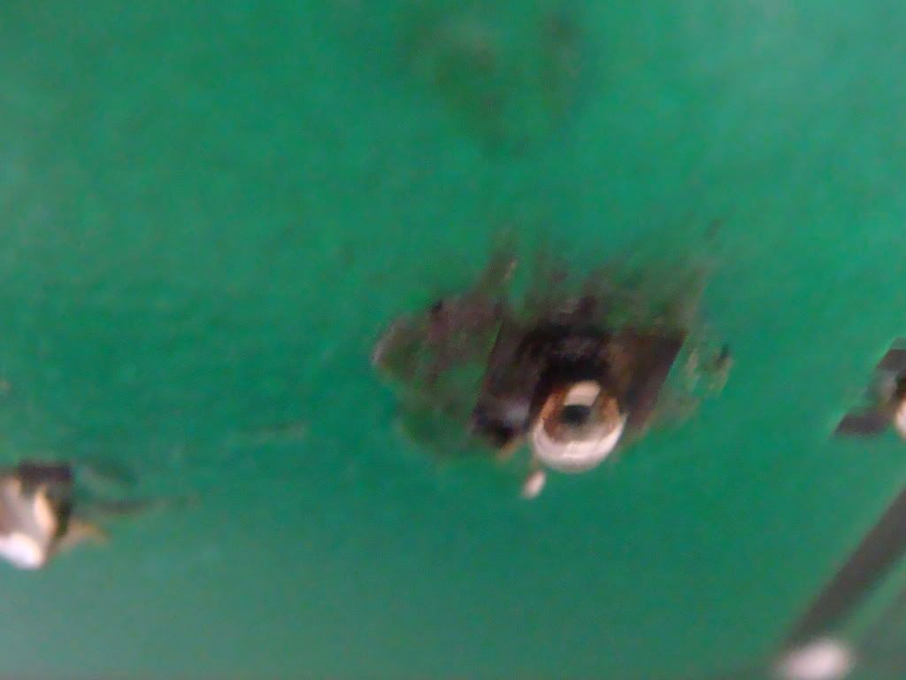
you lifted the pad on this side of the board that's why the solder didn't flow like it should. good news is that the electrical connection isn't on this side of the board, it is on the top side. just make sure the solder flow looks good on the top side and you will be fine...
a bit of rubbing acohol and a tooth brush will clean up the flux..
Posted: Fri Nov 28, 2008 7:23 pm
by Thumper88
yesterdaysyouth wrote:you lifted the pad on this side of the board that's why the solder didn't flow like it should. good news is that the electrical connection isn't on this side of the board, it is on the top side. just make sure the solder flow looks good on the top side and you will be fine...
a bit of rubbing acohol and a tooth brush will clean up the flux..
not easy to do since I'm pretty sure that's a capacitor that's missing the pad...
Posted: Fri Nov 28, 2008 9:15 pm
by MW3
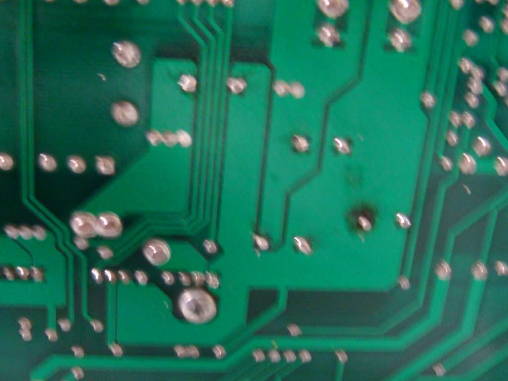
Post more pics...
Maybe Roland can chime in.
He used to fix a few PG amps in his spare time.

Posted: Sat Nov 29, 2008 9:15 am
by denisl
Posted: Sat Dec 06, 2008 1:33 pm
by denisl
anyone? Do I need to get the board reparied?
C - you out there?
Posted: Sat Dec 06, 2008 3:02 pm
by Jacampb2
The board should be repaired, but doing so may not be feasible... As stated above, the actual connection is on the top side of the board for those pads. If the solder flowed, then it hopefully took on the top side. Unfortunately, there is no way to check with caps, as they cover the top pads.
If you google PCB repair, there are a number of companies that sell kits and supplies to do repairs such as you need. There are also a number of companies that will do the work. I have no experience with these "kits" so I cannot attest to how well they work. There are also things out there for prototypers like tiny copper rivets, which can be used to put vias in a home made board, it is possible that you could find something like that that has a through hole made for repairs.
Good luck,
Jason