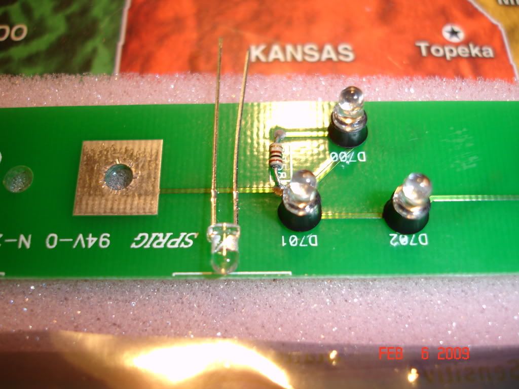
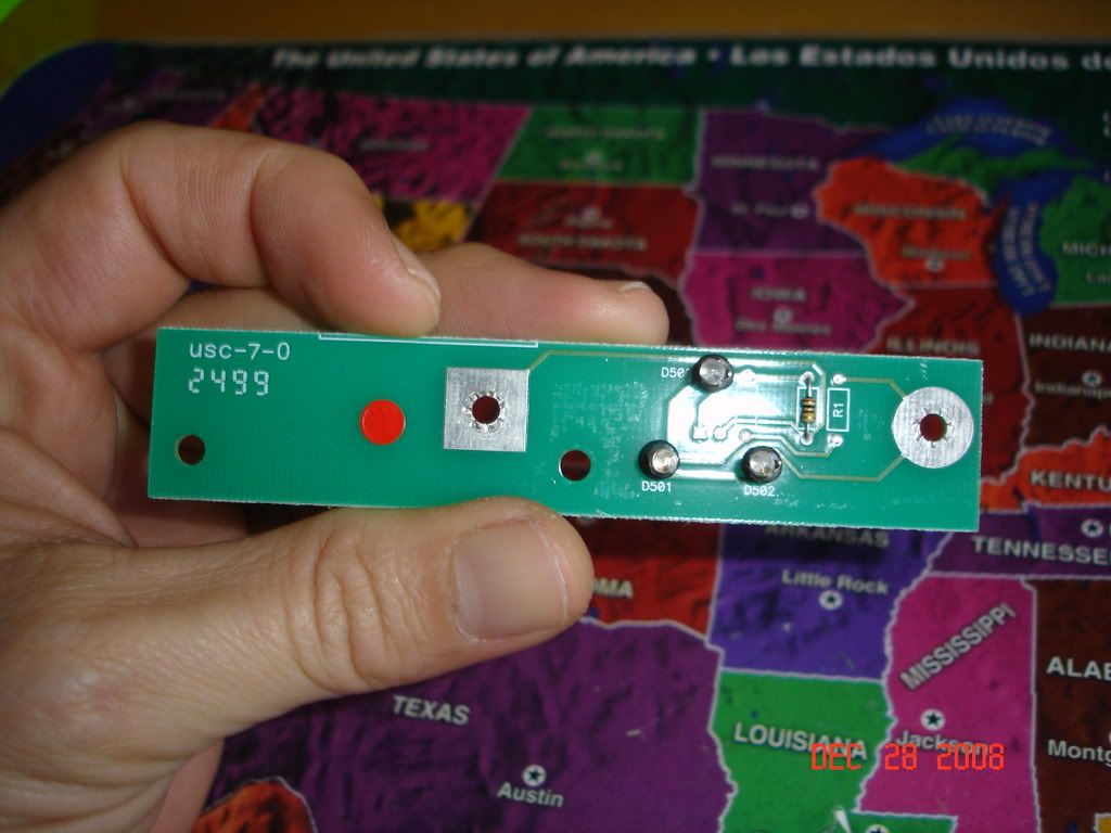
pics worth a thousand words!!! if ur ti led pcb has the resistor as pictured to the top left you solder all 3 leds in this way, longer left lead goes in left, shorter right lead to the right, if ur pcd has the resitor to the top right, then the opposite way-hope this helps, ita alot better than typing it all out as earlier-C
as she walked out the door she expressed, 'enjoy your amp addiction'
It looks like you tinned the leads there as well? They shipped the leds today and it is supposed to be 2-3 days to az. I was looking forward to mounting my amp and starting my amp rack but I do not want to have to pull it back out to fix it so I started on the power wires instead. I made my wires to replace my big-3 power wires but it was dark so I will finish tomorrow.
nope the leads came that way-wow, did u order them from newark? i live in florida, and they ship to me from South carolina, and i usually get their items in 2-3days too, well thats awesum and good luck-why dont u go ahead and remove the amp cover, and unscrew the led board? u could goto rs and get the cheap desolder iron with bulb, and have the old stuff sucked out, and the board ready to go when the new leds arrive? just my 2 cents for efficency
as she walked out the door she expressed, 'enjoy your amp addiction'
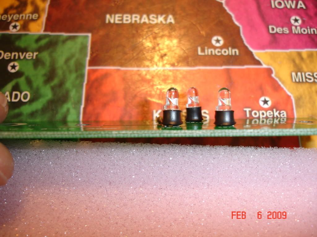
the shipment was delayed 2 days due to the weather but they came in today. I was amazed how many screws they used to hold the top on, and 4 different types made it fun to organize to put bach together. A nice long strip of 4" wide masking tape made it easy though and I was able to get all the screws matched up correctly. The resistor on my board was on the other side, and the leds were also backwards from yours. I was a little worried at first but I matched them up correctly. I see why these were limited edition as it is a PIA to put back together. Between the paint trying to chip off of the edges, the led being 1mm off from the holes, and the bass adjustments on the front it was not fun to make sure it was aligned correctly and I can't tell you how giddy it made me when all 3 leds finally dropped into their hole in the top.....
Before the leds came in today I was able to run most of the wires although I need a hole-saw to make a hole for the 0 awg and run speaker wires. The majority of the work is done so hopefully I can finally get to hear it!
so did they fire up?(new leds come on?) were you able, with new ones, to get them lined up better than the originals? ( yeah , on the le octane, for some reason , is ALOT harder to re-install the cover, but just takes more time and patience than an regular Ti-well good luck, and youll be psyched once they fire up-
as she walked out the door she expressed, 'enjoy your amp addiction'
I only have an 8 amp power supply that I normally use to charge my rc airplane batteries and was worried that the caps charging could take more then that. I figured it was fuse protected and couldn't wait anyway, they took almost 15 secs to light up but yes when they did the living room never looked better......
If the weather holds up for another day or two I should be able to finish installing her..... The 2nd install bay I worked at sold Pg and that was were I really fell for it. Unfortunatly the place paid diddly so I never had a chance to be able to buy one even at cost. 5 yrs after that I had me electronics degree and a job that I could afford the amp with but then didn't have the time or energy to install it. I have been waiting to hear her for 7 yrs now.
again I thank you as if it were not for your pics I would have been on the phone with a place I know that could have done the repair. While I have a degree in electronics I have always tried to stay away from the repair tech side as the little bit I have done has just never been fun.
well, ive been able to figure out they made 2 different led pcb, ,first pic in the begining of this posts shows the resistor to the right of the leds, then this pages picture has a different board for the resistor to the left-now, the first pic on page 1 in this thread ,that led pcb came out of a ti600.2, then this pages board came drectly from pg-im pretty sure the pcb are interchangeable, as long as you have the leds soldered in correctly-depending once again which direction the resistor is in-(if that makes any sense to you-Ive had to do 3 of these recently)
as she walked out the door she expressed, 'enjoy your amp addiction'
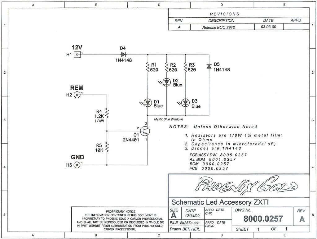
Well, I don't know as much about it as you, but I know there are 3 if not 4 different schematics. I know the one I have is for the 500.4 and 600.2. Just trying to contribute.
I remember the board on mine said 4201. I took some pics with my phone that I will try to load later. my resistor was to the right and I was able to look inside the leds to see that they were backwards from yours. all the boards make their contacts via the mounting screws and they can arrange them anyway they want as long as the leds match up and the set screws are tight. Might not be bad to have a directory of pics of the different boards for future repairs.
cojones wrote:Well, I don't know as much about it as you, but I know there are 3 if not 4 different schematics. I know the one I have is for the 500.4 and 600.2. Just trying to contribute.
Corey, im not trying to sound like a prick, yes if u have more info, then please send it, i cant even read that schematic! im a visual learner, meaning i looked at what i had, and figured it out that way-I am no electronics expert, and u know that from previous coversations-but am willing to try and learn-
as she walked out the door she expressed, 'enjoy your amp addiction'
LEDs go one way... they have a notch on one side. So if you are replacing it, just make sure you put the notch of the new LEDs in the same direction. Same as capacitors, or regular diodes.
the schematic between the 3 will probably show very little difference as it is not like they have added or subt componants, only moved them around a little on the board.
I too am a visual learner but I do have an degree in electronics and some experience to back me up.
Well from what Matt and Bill told me, its a big difference, as some leds were wired in series and others parallel.
Everything I've posted about this has come from PG tech dept. I'm just trying to help, as I need my leds replaced too, and I want this thread to have all the information available for anyone else.
cojones wrote:Well from what Matt and Bill told me, its a big difference, as some leds were wired in series and others parallel.
Everything I've posted about this has come from PG tech dept. I'm just trying to help, as I need my leds replaced too, and I want this thread to have all the information available for anyone else.
hear you on that;irregardless which board it is for leds, just look at the way the "BAD"or "BURNT" out ones are soldered in , and just do the same, in my limited experience, theyve all been going same direction, now, im not an electrical engineer, but im pretty sure the resistor helps with the voltage, and what your refering to as far as series, parrell, if im understanding you-just take ur amp cover off on the 500.4 right? look real close, youll see all three are in same way-this is what ive observed on a ti600.2, zx600.2ti, zx475ti, ti 500.4, ti 1200.1, and even the le octane
as she walked out the door she expressed, 'enjoy your amp addiction'
Matt from ts is who emailed me that schematic- but im pretty sure he couldnt even read it, b/c b4 i starting delving more into it, it was difficult for him to answer my question on/about it-but he sent it 2 me out of the blue weeks after the conversation, so i know he was trying to help out in his own way-just shocked it hasnt posted more here? also googling led helped me out alot, gives more detail on the anode/cathode technicallity of them-im sure ull have no issues with replacing them cojones,
as she walked out the door she expressed, 'enjoy your amp addiction'
I agree that replacing the LEDs verbatim is a good idea, But determining there wiring configuration as series or parallel, that is in the circuit board. You can wire subs in series or parallel and have the logos face the same way. As for the amps you've had experience with, you should have seen only 2 configurations. I belive Matt said the 350/400 share a board then the 500/600 and then the 1200/1000, I'm not sure about the 800.
Bill is the guy that knows more about the board config. Bill also told me that the LEDs are seldom the problem. He told me what to look for but I don't know how to explain it in text, I'm a visual teacher.
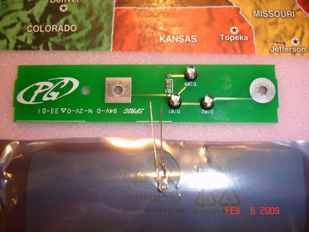

 this is the 1 i call resistor to the right on the led pcb