
Hey guys, I am thinking about making a substitute for the dd5/dd10 that is less costly. They seem to have INCREASED in value, compared to their original price. They are great, but I'm not sure I want to spend $150 - $300 for one. Plus, they are kind of big. So, I started designing a stripped down DDx. I've got one completed PCB design for a simple device:
Block 1 (Input)
B+
B-
R-in
Block 2 (Amp turn-on)
R-out x 4
The amp remotes would be relay switched from B+ and include approx. one second turn-on delay.
Block 3 (DSP supply)
B+ x 4
B- x 4
R-out x 4
All power requirements for 4 low-power devices like EQs or other signal processors.
Block 4 (Fan supply)
R-out x 4
B- x 4
Rather than run them ganged from one of the low-power slots, I included dedicated fan power distribution. R-outs would be used instead of B+ since OEM fans typically don't have remote turn-on inputs. Another option I am considering is replacing these with more Block 3 style outputs for more flexibility.
Notes
The relay would probably be of 20A capacity. Block usage would probably be something like:
Block 2 = 400ma (~100ma per amp R-out)
Block 4 = 6a (up to 1.5a per fan)
Block 3 = 12.4A (up to 3a per B+ and 100ma for the R-outs)
Looking at using two-piece type connection blocks, so that the part that connects to your wiring can be detached to make it easier to wire, then snapped back on to the unit.
Features I am considering
Internal fusing for all outputs
Power LED
Fan status LEDs
Fan speed pot(s)
Signal processor power LEDs
Turn-off delay for signal processors (looking like this may be tricky and is of dubious actual value)
I am trying to keep size, complexity and cost to a minimum, lest I defeat the purpose of the project. I am targeting a size of less that 6" x 4" x 2". It will be difficult to do using prototyping boards, but I think doable. If there were enough people interested, I would have custom PCBs made up. I priced some out, and you really need to order a batch. 1 pcb = $53, 4 = $53, 9 = $80. Or something like that, I don't remember the exact prices. Obviously you need to get a handful of them to make it worth it. If I don't add on LEDs or pots, just make it as simple as possibly, and had an order of, like 10 units to keep PCB costs decent, the materials cost would be something like $20. Assembled, I would probably be able to do them under $50. Possibly well under $50. Depends on how long it actually takes to build them and how many components (esp. PCBs) I am able to order, and doesn't include any fancy paint work. I'll probably offer a plain paint scheme with a choice of colors. Maybe I'll look into finding a screener around here and get a phorum logo and connection labeling on them. Hehe, the PhoenixPhorum.com DDx!
So, all that said, are people interested in something like this? If so, let me know, and I'll figure out if it feasible. If enough are interested, I'll get to work on a prototype and make sure it works as intended, then we'd see about getting the production model finalized. Not sure if I'd need deposits before committing to getting supplies and building them. Generally speaking, I don't think I'd have to worry about the guys on here changing their mind or something. If interest is high (like, high enough to where I would consider posting them on other forums), I'd probably do some sort of introductory price for phorum members.
What do you guys think?
P.S. I have sourced pretty much everything except enclosures. Obviously there are plenty of generic project boxes out there, but I'd like to find some sort of aluminum housing that is more applicable to the device. Not to mention the whole issue of connection cutouts and crap.
Remote/accessory power distro (product interest?)
Remote/accessory power distro (product interest?)
Octane Limited Edition (maybe for sale soon)
MS2125TA MS2250TA (Thanks Wakeup)
MS2125 x 2 (white, need caps)
MS275 (Burr Browns and fresh caps - Thanks, Matt)
MS2125TA MS2250TA (Thanks Wakeup)
MS2125 x 2 (white, need caps)
MS275 (Burr Browns and fresh caps - Thanks, Matt)
I may buy a dd5 or dd10 still, if I can get a solid deal. Regardless though, if there is enough interest to make it practical I am still down with designing them and offering them in either kit or completed form. I actually like designing gadgets and stuff. It helps fill the down-time at work, which I have a lot of due to the nature of my work.
Octane Limited Edition (maybe for sale soon)
MS2125TA MS2250TA (Thanks Wakeup)
MS2125 x 2 (white, need caps)
MS275 (Burr Browns and fresh caps - Thanks, Matt)
MS2125TA MS2250TA (Thanks Wakeup)
MS2125 x 2 (white, need caps)
MS275 (Burr Browns and fresh caps - Thanks, Matt)

-
waynehead

- No, you're a towel.
- Posts: 938
- Joined: Fri Aug 01, 2008 8:26 am
- Location: Butthole of Ohio
a DD5 and DD10 is a multiple delay remote device. So you turn on your car and your head unit turns on, then your processing equipment, then your amps and cooling fans and so on. To avoid that annoying turn on noise and avoiding damage on account of that noise. I believe it also has leds but am not real sure. never have been able to afford one. 
We don't need no stinkin' bass boost!
What the dd5/dd10 does is this:Stryker wrote:I'm not actually sure what something like a dd5 or 10 does. Could someone explain briefly. i would probably buy one cause i have like 5 things being turned on by the deck remote wire and i beleive your idea helps with this. so possibly count me in.
- You hook up power, ground, remote, just like an amp.
It then has several remote turn-on outputs for your amps, all at proper power levels, since it is in effect "boosting" the remote wires power to handle more devices better.
It also has 5 or 10 more outputs for low power devices. Each one of these outputs has power, ground and remote for each device. Things like EQs, crossovers, fans, lights, whatever you want, provided it is a relatively low power device. It also has internal fuses for all of these devices. I forget what the max current draw it supports is. I think it comes w/ 1 amp fuses, but the manual says you can use up to 10 amp fuses for each output. Not sure what it's total combined current limit is, but it has 4awg power and ground inputs, so probably fairly high.
Finally, it also has adjustable turn-on delay for the amps, from 0 to 8 secs, and adjustable turn-off delay for the other devices, again from 0 to 8 secs, i think.
Octane Limited Edition (maybe for sale soon)
MS2125TA MS2250TA (Thanks Wakeup)
MS2125 x 2 (white, need caps)
MS275 (Burr Browns and fresh caps - Thanks, Matt)
MS2125TA MS2250TA (Thanks Wakeup)
MS2125 x 2 (white, need caps)
MS275 (Burr Browns and fresh caps - Thanks, Matt)
-
bretti_kivi

- Shutterbug
- Posts: 1595
- Joined: Tue Aug 26, 2008 1:06 pm
- Location: Päijät-Häme or Uusimaa
For me...
- one main input
- two to three types of output:
- "high power" - up to 5A - for DSP x 1
- medium power - 2 A - for fans x 2
- low power for remote turnon - but several of these, i.e. 4-5
would be excellent.
If you could fuse it, that would be monster. Mini fuses. Backlit with a LED or three
So, reading your initial post again - yes, like that, but I'd take it up to 5 amp outputs.
Enclosure: hifi2000.it - the galaxy ones - then a machinist to do top panels. You could get those done by Schäffer, but it might be expensive, I'd have to see an example and price it up.
Sounds really good, I think you'll get lots of interest. Where were you going to get the PCBs done?
Bret

With myself included, it sounds like I should be able to count on at least five units, and four is the minimum that it is at all reasonable for me to make. I'd probably do 9 though, as that drops the PCB cost another big chunk, and I should be able to eventually move them.
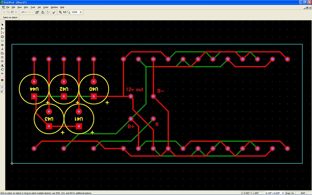
Here is a layout of a basic design I threw together real quick on a 2-layer PCB. It has 5 amp turn-on outputs with caps to delay amp turn-on by about 1 sec. There are also 4 low-power device outputs on each side for a total of 8 devices. With the empty area on the right, it gives me a decent spot to mount the relay without needing to increase the enclosure footprint beyond the board footprint. The size of this board is 3.9"x1.6", so for this device the enclosure would probably be about 4"x2"x2".
The PCB supplier I am looking at is pad2pad.com. They have their own simplified PCB design software that is suitable for realatively simple devices like this.
Really, I'd like to incorporate some more advanced features of the type that will have minimal impact on the size and cost of the product. So long as the batch size is 9 or more, and provided I can find a reasonably priced enclosure that meets the needs of the project, a sub-$50 "retail" cost should be easily doable. For those on a tight budget and with the ability to assemble the device themselves, a diy kit may be an option. I'll know more as things progress.
The main hurdles I have right now are figuring out the best connectors to use and finding a suitable enclosure, preferably that I can have cut to spec. The interest shown thus far is encouraging. Correct me if I am wrong, but the DD5/10 is the only product I am aware of for this application, yes? If so, that means I may be able to generate enough interest in the device to really bring cost down.
Any ideas you may have, please post them.
Octane Limited Edition (maybe for sale soon)
MS2125TA MS2250TA (Thanks Wakeup)
MS2125 x 2 (white, need caps)
MS275 (Burr Browns and fresh caps - Thanks, Matt)
MS2125TA MS2250TA (Thanks Wakeup)
MS2125 x 2 (white, need caps)
MS275 (Burr Browns and fresh caps - Thanks, Matt)
-
fordtough1

- Twisted's Boyfriend
- Posts: 1438
- Joined: Fri Feb 23, 2007 7:07 pm
- Location: Are we there yet?
Oh, and I forgot to mention, in the example ckt I posted, the delay section for amp turn-on isn't complete, I am still working on that, so I just completed the traces so I'd have something to show you guys.
Octane Limited Edition (maybe for sale soon)
MS2125TA MS2250TA (Thanks Wakeup)
MS2125 x 2 (white, need caps)
MS275 (Burr Browns and fresh caps - Thanks, Matt)
MS2125TA MS2250TA (Thanks Wakeup)
MS2125 x 2 (white, need caps)
MS275 (Burr Browns and fresh caps - Thanks, Matt)
Given all you've done/are doing for me, I think I should be able to work something out for you when the time comes.Wakeup wrote:I might be interested if the price is right...(jobless sux...) and of course looks could be helpful!
Octane Limited Edition (maybe for sale soon)
MS2125TA MS2250TA (Thanks Wakeup)
MS2125 x 2 (white, need caps)
MS275 (Burr Browns and fresh caps - Thanks, Matt)
MS2125TA MS2250TA (Thanks Wakeup)
MS2125 x 2 (white, need caps)
MS275 (Burr Browns and fresh caps - Thanks, Matt)
Well, I learned about delay ckts for turn on and turn off today. Should be able to implement them without too much of a cost increase. I am looking at using pots on them, so they'd be adjustable, but most likely I would make it a "remove the cover" type adjustment to keep enclosure costs down.
This design handles 6 amps with turn-on delay and 8 other devices w/ power, ground and turn-off delay. The PCB is about 4"x1.5". With a little effort, that means a 4"x2"x1.5" enclosure would be doable. However, this is relying on 2.54mm pitch on the headers, which may be too tight. I could keep size down by having wiring on two sides, but I would prefer to keep all wiring to one side. It's likely that the final device would end up around 6"x3"x<2"
Here's a look at my latest PCB. Nothing near final, or even prototype stage, but perhaps interesting none-the-less. The mess on the left is the turn-on delay ckt., and the mess on the right is the turn-off delay ckt.
Octane Limited Edition (maybe for sale soon)
MS2125TA MS2250TA (Thanks Wakeup)
MS2125 x 2 (white, need caps)
MS275 (Burr Browns and fresh caps - Thanks, Matt)
MS2125TA MS2250TA (Thanks Wakeup)
MS2125 x 2 (white, need caps)
MS275 (Burr Browns and fresh caps - Thanks, Matt)
Yeah, I was looking at doing it that way too, though I worry that the cap may delay off as well as on. The ckt I am using at the moment prevents that, and also some other stuff with voltage drops and stuff. I'm still reading up on exactly what the 3 transistors in that ckt do to thinks. Oh, speaking of the transistors, that turn-on delay ckt has some of the transistors in a Darlington configuration.ttocs wrote:I think all the turn on delay is, is a cap and a resistor. A pot would make it adjustable.
Octane Limited Edition (maybe for sale soon)
MS2125TA MS2250TA (Thanks Wakeup)
MS2125 x 2 (white, need caps)
MS275 (Burr Browns and fresh caps - Thanks, Matt)
MS2125TA MS2250TA (Thanks Wakeup)
MS2125 x 2 (white, need caps)
MS275 (Burr Browns and fresh caps - Thanks, Matt)
-
thedeal7235

- Posts: 1866
- Joined: Fri Jan 25, 2008 7:49 pm
- Location: Sanford, Florida(orlando area)
-
fuzzysnuggleduck

- Soy Milquetoast
- Posts: 4423
- Joined: Wed Dec 06, 2006 1:08 pm
- Location: The best place on earth
- Contact:
I am working on having both turn-on delay for the amps and turn-off delay for the processors. I found an easy way to do it, using a single module, but they are too costly, imo, so I am working on doing it the hard way, which really isn't all that hard, it just means I have to learn a bit more stuff to do it right. As to fusing, I intend to have internal fusing for all of the processor/acc. outputs. At first I wasn't sure there'd be room, but I am now realizing that the space required to get all the connectors on there is greater than what is required for the circuitry.fuzzysnuggleduck wrote:Are you fusing each of the power outputs?
Also, will there just be turn on delay for the amps or will there also be turn off delay on the processors?
Octane Limited Edition (maybe for sale soon)
MS2125TA MS2250TA (Thanks Wakeup)
MS2125 x 2 (white, need caps)
MS275 (Burr Browns and fresh caps - Thanks, Matt)
MS2125TA MS2250TA (Thanks Wakeup)
MS2125 x 2 (white, need caps)
MS275 (Burr Browns and fresh caps - Thanks, Matt)
Thanks for the PM w/ the pics. Should help me out some to see how PG's version looks.thedeal7235 wrote:Grim0013, let me know if u want a pic of the dd10 with the cover off to see inside?!(btw, after this project u need a 5guys burger/fries)
Octane Limited Edition (maybe for sale soon)
MS2125TA MS2250TA (Thanks Wakeup)
MS2125 x 2 (white, need caps)
MS275 (Burr Browns and fresh caps - Thanks, Matt)
MS2125TA MS2250TA (Thanks Wakeup)
MS2125 x 2 (white, need caps)
MS275 (Burr Browns and fresh caps - Thanks, Matt)
-
fuzzysnuggleduck
- Soy Milquetoast
- Posts: 4423
- Joined: Wed Dec 06, 2006 1:08 pm
- Location: The best place on earth
- Contact:
Cool! Sounds like a complete solution, then.Grim0013 wrote:I am working on having both turn-on delay for the amps and turn-off delay for the processors. I found an easy way to do it, using a single module, but they are too costly, imo, so I am working on doing it the hard way, which really isn't all that hard, it just means I have to learn a bit more stuff to do it right. As to fusing, I intend to have internal fusing for all of the processor/acc. outputs. At first I wasn't sure there'd be room, but I am now realizing that the space required to get all the connectors on there is greater than what is required for the circuitry.fuzzysnuggleduck wrote:Are you fusing each of the power outputs?
Also, will there just be turn on delay for the amps or will there also be turn off delay on the processors?
SOLD: '91 PG 4Runner
-
bretti_kivi
- Shutterbug
- Posts: 1595
- Joined: Tue Aug 26, 2008 1:06 pm
- Location: Päijät-Häme or Uusimaa
looking very good. What's the next price break? I'm sure you could (I could) sell a whole bunch of these. But it needs to look good and you've forgotten the purty lights
By all means put the delay change on a pot on board that you have to take the lid off / underneath to change. How often would you need to change that, anyway?
Bret
By all means put the delay change on a pot on board that you have to take the lid off / underneath to change. How often would you need to change that, anyway?
Bret