All pictures here can be seen in high resolution on my pics site as well: http://photo.stipud.com/v/stereo/MPS2500/
So, here we are at the start of the game. Remove your bottom plate by removing 6 screws (in my case, all the screws were sheared off already

Start by removing the endcaps (5 screws each), and all the connected parts. The speaker wires clip right off the board, and there are two screws that secure the shiny gold power rails (make sure you thread them back in so you don't lose them).

I started pulling the powersupply capacitors in Jim Truett style:
http://phoenixphorum.com/viewtopic.php?f=6&t=8276
Unfortunately I wasn't so lucky getting them out. My caps took lots of force to remove (enough that I needed Wendy to hold the amp down while I pulled with both arms!), and a few of them broke off before they were removed. I am not sure I can recommend this technique based on the difficulties I had.
04/21/09 Edit: Eric D recently recommended rocking the capacitors back and forth gradually to get them out. Even if the leads break off, it's better than damaging the VIAs that connect the top and bottom of the board. You should avoid pulling them straight up like I did.
As you can see though, there's lots of electrolytic fluid under them.

To get the transistors off, unscrew them slightly, and insert a pointy screwdriver under the top corner, then press in and it should pop right up. Be gentle with the little ones; they require far less force.

Once you've got all the transistors lifted off the board, you can finish removing the screws. Make sure you keep them organized so you don't lose them, or forget which goes where. Take lots of pictures along the way as a reference!

And here's what you end up with. To finish it off, there are 9 screws that connect the board to the heatsink. Remove them, and it will lift right out!

Here's the side we're not so familiar with. As you can see, it rests nicely atop the torroids, so you don't have to worry about bending the transistors at all.

And here's the naked heatsink. As you can see there's a sheet of plastic that lies between it and the board, to keep it from shorting out. You can also see that there's some crap under mine... It looks like this amp has had a bit of coffee spilled in it

Unfortunately I didn't have my camera for this step...
Start by removing the leftovers from the powersupply input caps. I did this with the amp hanging over the corner of my desk, pliers under the table (pulling down) and heating up the solder from the top, where you can see it and not make any mistakes.
The rail caps need to be removed the old fashioned way. Heat up one pad JUST until the solder gets fluid (then stop heating!), and pull the cap down on that side until it stops. Then do the same on the other side. Wiggle back and forth heating as little as possible (if you feel the amp getting too hot STOP or move to a different cap for a minute). Eventually you will hear them POP as they snap out of the circuit board.
After that, you should remove the solder from the holes. This will make installation much easier. Just use some solder sucker (braided copper) to pull the solder off of the board, leaving nice open holes to feed the caps through.
Once that's done, you can clean the amp. I used 99% isopropyl alcohol and a toothbrush. DO NOT USE 70% ISO... it will leave all kinds of crap residue. A neat trick is to get some air in a can. Once you've got the amp cleaned up, all you have to do is blow the iso off. I also let it dry overnight to make sure everything was dried out perfectly.
Which brings us here... there's a bit of discoloration around the PS caps, but the rest of the board cleaned up reasonably well. I could have gotten it cleaner but I am pretty lazy


I also cleaned all the coffee stains and thermal paste off of the heatsink and plastic sheet. For this, I just used some generic Lysol household cleaner, followed by isopropyl where the transistors mount to, to make sure there's nothing that will impede the conductance of heat.

Here's a closer look at the rail cap section. You will see there are little rings where the caps wear on the board. This amp was probably mounted to a sub box.

As you can see here, the rail caps I bought were a bit shorter than the factory parts. I could tell the top of my factory rail caps was scuffing on the underside of the bottom plate, so I erred on the small size.
I bought these: http://search.digikey.com/scripts/DkSea ... e=P6667-ND
But you could probably fit: http://search.digikey.com/scripts/DkSea ... e=P6669-ND
Since these rail caps are 35mm tall, moving to 35mm power supply input caps is also possible. I still prefer to stick to 105*C caps since it's not unlikely for the amp to get that hot.

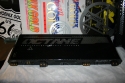
So now we're ready to take the amp apart. One last look...


Here's an AWESOME trick I learned from Cecil that I highly recommend. Put a bead of RTV silicone down the trough in the middle of the powersupply capacitors. This will keep the two sides separated if the capacitor does start to leak, so it will make it less likely to short out. It also acts as a vibration dampener, AND it makes the caps super easy to install, since they stick in place.
Pull the leads through, and apply solder! Easy as pie! When you're happy with everything, and you've made a satisfactory bond between the amp and the board (make sure the solder forms a full bubble which adheres the wire), you can snip the leftover leads off.

The rail caps are even easier, since they snap into the board. You just clip them in place, and apply solder. Hooray! Cap replacement is done!

Now that you've finished, it's time to clean up the flux. Fortunately I got pictures of this part. Apply a bit of isopropyl to your toothbrush, and wipe it away. Finally, spray it with canned air, and it will disappear!


Then you should be left with nice clean solder. I embarrassingly did a poor job of cleaning the old solder out, and I used generic stuff to replace it, so you can see it's not very shiny


Now comes the hard part -- reassembly (really, this took me the most time!).
Cut up all of your sil-pads to fit the transistors nicely. The sil-pads I got from Nico were the perfect size for the big output BJTs, but they needed some cutting on all the smaller transistors. Make one good cut as a template, and then you can stack a few up and cut them together. It's better to err on the large side, rather than making something too small. Finally, test fit all of them. You shouldn't be able to see any exposed transistor.

Once you've got your sil-pads ready, screw the board back in. You can start connecting the transistors now. Gently lower the sil pad underneath the transistor, and line the screw hole up. As you screw the transistor down, use a screwdriver or fingertip to keep the sil-pad from being twisted by the screw.


Make sure all your transistors are sitting FLUUUUSH. If they are angled or not pressing down at all, then you risk blowing them up. If you find they are at an angle, don't panic! You can simply heat up the solder at their base, and press them down.


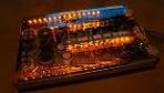
Here's the finished product!


Unfortunately all this fiddling around ended up breaking one of the RCA wires off. If you've gotten this far, it's a breeze to solder back together. I recommend that you learn from my mistake and tape it up before you have to do this, however!


Now it's time to reassemble the amp. Screw the powersupply rails back in, connect the remote wire, and reinstall the endcaps.


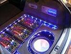
Finally, what we've all been waiting for.... I must admit my heart was racing at this point. You should probably be smart and install a small fuse before you do this, but what can I say, I was impatient

So there you go folks. Sorry I didn't get pictures of the actual soldering, but it's hard to hold a cap, solder, an iron AND a camera all at the same time