Blown Ti1000.2

Need help with your car stereo system? Have a technical question? Post here.
Post Reply
User avatar
Jacampb2
Mad Scientist
Posts: 1563
Joined: Sat Apr 19, 2008 11:57 pm
Location: Beaverton 48612

Blown Ti1000.2

Post by Jacampb2 »

Finished up my ZX450, a Ti400, and started in on my blown Ti1000.2 today. This thing is in just a bit worse condition than my Ti1200.1 that you guys saw me attempt to repair a few months back. Ti1200.1 repair, clicky. This 1000.2 has virtually the same damage, but worse. Same side of the board. I am beginning to think that the supply farthest from the power connector gets current starved while running a low impedance load. This amp has no other damage that I can find to have caused this meltdown.

Anyhow the pics pretty much speak for themselves. Someone tried to do a butch repair before I got it, and it was probably worse from that then it would have been had it been left alone.

Anyhow, here are the pictures. I have my work cut out for me again...

Image

The ripples in the copper are not a camera artifact. It has totally lifted from this part of the board. Really charred bellow...

Image

Bottom of the board got hit the hardest. Again, really jacked up and charred with lots of loose copper.

Image

Last little bit I had time for before shutting down for the afternoon. Chopped off the damaged part of the board.

Image

New chunk of PCB drawn up in eagle cad. I will be cutting it on the mill tomorrow. Then it is just a matter of soldering it in, making it physically stable, and seeing if she will power back up.
M: M100, M44 for a custom amp project
Zx: Zx500, Zx450, Black Zx350
ZxTi: 4 Zx600Ti's, 1 Zx400Ti
Ti: 5 800.1's & 900.7 for a custom amp project. 1 1200.1, 1 1000.2
Tantrum: 2 1200.1's, 1 600.4, 1 500.2
XS: XS6600
User avatar
stipud
Voltage Ohms
Posts: 14719
Joined: Sat Nov 26, 1983 4:00 am
Location: Burnaby, BC
Contact:

Post by stipud »

I will be seriously impressed if (who am I kidding... WHEN) you get that thing running.
User avatar
Jacampb2
Mad Scientist
Posts: 1563
Joined: Sat Apr 19, 2008 11:57 pm
Location: Beaverton 48612

Post by Jacampb2 »

I almost got far enough to test tonight, but I had a trace that got bridged somewhere and I had to hunt for the errant path for an hour. I got the new piece cut out. The patch piece is in place now, the joint between the boards is made with a bunch of used solder braid. Probably more copper in the joint than used to be in the copper layer. I used 2oz copper board since this is a high current area.

I am back to work tomorrow, so I wont have time to work on it for a while.

Pics:

Image


Image


Image


Image

Oh yeah, and I fubared the two traces for the thermistor. I will have to run some jumpers for those.

Later,
Jason
M: M100, M44 for a custom amp project
Zx: Zx500, Zx450, Black Zx350
ZxTi: 4 Zx600Ti's, 1 Zx400Ti
Ti: 5 800.1's & 900.7 for a custom amp project. 1 1200.1, 1 1000.2
Tantrum: 2 1200.1's, 1 600.4, 1 500.2
XS: XS6600
User avatar
Stryker
Posts: 1567
Joined: Tue Oct 21, 2008 3:22 pm
Location: Calgary

Post by Stryker »

thats awfully impressive that you can do these sort of things...... :shock:
screw car audio, I'd rather go fast....errr, wait a minute.
User avatar
Jacampb2
Mad Scientist
Posts: 1563
Joined: Sat Apr 19, 2008 11:57 pm
Location: Beaverton 48612

Post by Jacampb2 »

No pics at the moment, but a brief update. I got the board all repaired, new Fets installed, gate drivers replaced and test fired it. Amp powered in thermal. I found one of the traces from the thermistor in the power supply I just fixed was blown out where it runs along the bottom of the board. I fixed it up, and test fired again. Right side comes up, left power supply (the one I am working on) does nothing. On a whim, I tried swapping out the PWM ic, nope, not it. I eventually found that I had followed the past owners mistaken repair attempt, and had the gate driver A06/A56 pair swapped. I swapped them around the right way, and the rails came right up. High current draw at this point so I shut it down and checked the outputs again. No bad outputs (same as the last time I checked) but I did find a pre-driver that had shorted. Swapped it up and it idles perfectly-- almost...

The amp however still did not work. The little red LED's on the board were not lit, showing that the power amp was not turning on. After a bit more work, I found the +15V rail was not coming up-- turned out to be a blown fusible resistor in series with the collector of the transistor which is used in conjunction with a zener diode to regulate the +15V rail. Swapped it, and bam the amp comes up.

Preliminary sound check and it sound okay, but needs the channel bias reset, as the PO turned the bias pots all the way down. I fuckered up and overbiased the right channel with no sinks in place and smoked some god damned expensive outputs. I will have to sort it out when I am back off work.

Additional problem I still have, it that the rails on the blown side of the board are stable but they are offset, the (+) 70 and (+) 60 volt rails are both down about 5V from their compliment. The amp is not exhibiting abnormal current draw, so I am not real sure what is causing the mis-match at the moment. When I find it, I will fill you all it :)

Later,
Jason
M: M100, M44 for a custom amp project
Zx: Zx500, Zx450, Black Zx350
ZxTi: 4 Zx600Ti's, 1 Zx400Ti
Ti: 5 800.1's & 900.7 for a custom amp project. 1 1200.1, 1 1000.2
Tantrum: 2 1200.1's, 1 600.4, 1 500.2
XS: XS6600
User avatar
stipud
Voltage Ohms
Posts: 14719
Joined: Sat Nov 26, 1983 4:00 am
Location: Burnaby, BC
Contact:

Post by stipud »

Holy shit that is an impressive amount of damage for one amp. I'll bet the previous owner's bodges probably CAUSED more issues than they solved :lol:

Kudos to you once again :beer:
User avatar
Misfire
Posts: 1170
Joined: Thu May 14, 2009 12:35 pm
Location: Oregon

Post by Misfire »

Impressive!
User avatar
wash with gasoline
Posts: 590
Joined: Thu May 01, 2008 10:44 pm

Post by wash with gasoline »

...but are you a gourmet chef and drive f1 cars in your free time? :lol: nice, everytime i read one of your posts im impressed. deff earned your title of the mad scientist
dry with match
User avatar
bogart
Posts: 1533
Joined: Thu Dec 18, 2008 6:30 pm
Location: SE PORTLAND

Post by bogart »

wow,,,total mess...I'd of written that amp off,,,but I don't know enough to even know what I am looking at....How did you learn this? I've been thinking about buying the amp repair dvd tutorial on ebay....looks pretty cool. just so I can get to where I can identify whats what and how to test without messing stuff up.

Do you get the schematics for the amps? How do you know what the bias pots are supposed to be doing? Oh so many questions and oh so little time
User avatar
Jacampb2
Mad Scientist
Posts: 1563
Joined: Sat Apr 19, 2008 11:57 pm
Location: Beaverton 48612

Post by Jacampb2 »

wash with gasoline wrote:...but are you a gourmet chef and drive f1 cars in your free time?
I used to be a short order cook, and I drive a rock crawler (<-----the avatar is my fun ride) in my spare time...

Does that count? :D
M: M100, M44 for a custom amp project
Zx: Zx500, Zx450, Black Zx350
ZxTi: 4 Zx600Ti's, 1 Zx400Ti
Ti: 5 800.1's & 900.7 for a custom amp project. 1 1200.1, 1 1000.2
Tantrum: 2 1200.1's, 1 600.4, 1 500.2
XS: XS6600
User avatar
Jacampb2
Mad Scientist
Posts: 1563
Joined: Sat Apr 19, 2008 11:57 pm
Location: Beaverton 48612

Post by Jacampb2 »

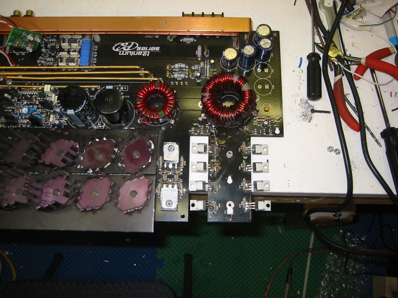
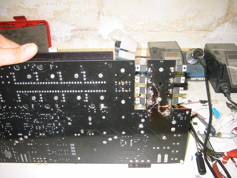
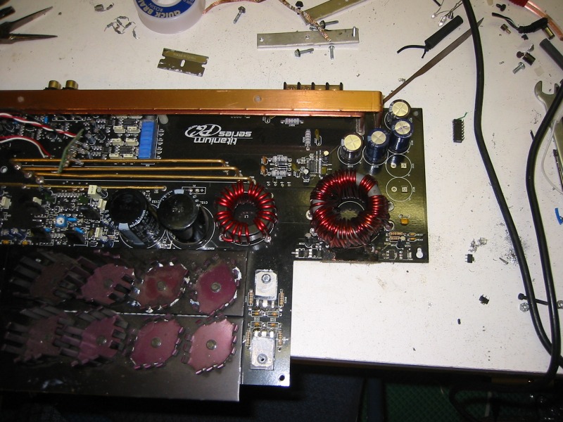
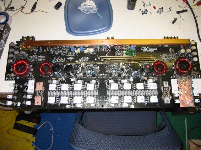
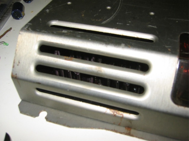
bogart wrote:wow,,,total mess...I'd of written that amp off,,,but I don't know enough to even know what I am looking at....
For me, the puzzle is half the fun. I have always liked fixing things, and I am a firm believer that with enough time and ambition anyone can learn anything.
bogart wrote:How did you learn this? I've been thinking about buying the amp repair dvd tutorial on ebay....looks pretty cool. just so I can get to where I can identify whats what and how to test without messing stuff up.
Most of my learning is done on my own, either by researching things online, or through various books. I have brought them up before, but G. Randy Slone has some excellent books, two that I own are: "The audiophile's project sourcebook" and "High-power audio amplifier construction manual". Both books are centered around home audio, but there is no real difference between home amplifier construction and mobile. The big difference is the SMPS. Douglas Self also has some excellent more in depth books on amplifier theory and design. And Marty Brown has some of the leading book on SMPS design and feedback theory. The stuff by Marty Brown should be considered middle to advance reading, it is geared more toward EEs. I also have met a few people on different boards who are willing to help and to teach. One gentleman I met on a machinist bulletin board of all places has been invaluable to my continuing education. He is a EE who works for a contract design house, and has never hesitated to make things make sense for me.

As for the Ebay course, I think you are talking about the BCAE guy. His free website is very informative, so I am guessing that his tutorial will be good stuff. I have considered buying it myself to see what it has to offer, but the $60 is enough to buy a blown PG amp and learn from experience :)
bogart wrote:Do you get the schematics for the amps? How do you know what the bias pots are supposed to be doing? Oh so many questions and oh so little time
Most of the PG designs are very similar. The actual triple darlington amplifier design from the early M's all the way through the Tis is pretty much unchanged. The power supplies is where most of the differences are. Even then, the same basic power supply architecture is used over and over, so once you figure one out, it puts you a long ways on top of the curve. As for Bias settings, all audio amplifiers have some form of bias setting. Very rudimentary amps may not be adjustable, but they all have it. Bias refers to providing a slight amount of base current to the output transistors so they are always biased toward conduction. Correct bias is critical to minimize crossover distortion (crossover as in when the outputs "cross over" 0v), incorrect bias will leave a "notch" in the output sine wave as it takes some current to begin to saturate the transistor, and during this time they are not conducting. If no bias is provided, there will be a flat area when the transistor starts to conduct, by providing bias, they are always ready to go, kind of like revving a race car at the line-- make sense?

Later,
Jason
M: M100, M44 for a custom amp project
Zx: Zx500, Zx450, Black Zx350
ZxTi: 4 Zx600Ti's, 1 Zx400Ti
Ti: 5 800.1's & 900.7 for a custom amp project. 1 1200.1, 1 1000.2
Tantrum: 2 1200.1's, 1 600.4, 1 500.2
XS: XS6600
User avatar
Jacampb2
Mad Scientist
Posts: 1563
Joined: Sat Apr 19, 2008 11:57 pm
Location: Beaverton 48612

Post by Jacampb2 »

All done. I found the blown output yesterday, replaced it, set the bias, and started cleaning the isolation plates and mini sinks. All cleaned up and back together-- working as well :D

Thanks for all fo the kind words.

Image


Image


Image


Image

Later,
Jason
M: M100, M44 for a custom amp project
Zx: Zx500, Zx450, Black Zx350
ZxTi: 4 Zx600Ti's, 1 Zx400Ti
Ti: 5 800.1's & 900.7 for a custom amp project. 1 1200.1, 1 1000.2
Tantrum: 2 1200.1's, 1 600.4, 1 500.2
XS: XS6600
User avatar
bogart
Posts: 1533
Joined: Thu Dec 18, 2008 6:30 pm
Location: SE PORTLAND

Post by bogart »

that is pretty cool, I am checking out the list of books. I ordered the tutorial and am going to see if I can get my comp guy over here to make us a few copies of it. It should be here this week so we'll see what it has to offer...a great deal for me I imagine.

so you cn'd the board area...can't that be done by hand as well...I've seen kits at fry's electronics but don't know...

good job man...impressive
brinrose
Posts: 34
Joined: Fri Jun 29, 2012 8:13 am

Re: Blown Ti1000.2

Post by brinrose »

Hi Jay I admire ur building new mosfet board and hope to learn how to make one I was hoping u can help me I need to replace the thermoistor in the pgzxti475 but can not seem to find any info on it it has c299 printed on it can u help me out
Post Reply