Can someone tell me?

Need help with your car stereo system? Have a technical question? Post here.
Post Reply
User avatar
jbob0124
Posts: 825
Joined: Sat Apr 24, 2010 1:09 pm
Contact:

Can someone tell me?

Post by jbob0124 »

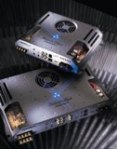
What are the wires in these pics for? I know the one in the first pic all the way to the left is the safety relay, but im not sure about the others. Im recapping my amps and im on my third amp. This is the first one I've seen like that.

Image

Image
User avatar
str3atwarrior
Posts: 806
Joined: Mon May 10, 2010 5:45 pm
Location: Drummondville, Quebec

Post by str3atwarrior »

What model of amp is it?
He appreciates your support but he aint beggin for it
User avatar
jbob0124
Posts: 825
Joined: Sat Apr 24, 2010 1:09 pm
Contact:

Post by jbob0124 »

str3atwarrior wrote:What model of amp is it?
Its a ZPA0.5
User avatar
smgreen20
Posts: 2873
Joined: Wed Dec 20, 2006 11:23 am
Location: Somewhere in Between

Post by smgreen20 »

The two wires attached t the switch is part of the remote turn on. The contacts need to touch completing the circuit turning the amp on. It goes under one corner of the plexiglass so when you put a screw in to hold the plexi cover on, it pushes the contact down. It's kind of a safety feature so no strands or the like will get into the amp while it's on.

The other wire I ?? My guess would be some sort of trace they couldn't manage to implement in the board layout so they made a jumper to bridge the connections ??
"ZPA's will have the same sound essentially as you get from the MS, they just feature a bigger shinier set of balls."

Install:
http://phoenixphorum.com/viewtopic.php?f=10&t=16998
User avatar
jbob0124
Posts: 825
Joined: Sat Apr 24, 2010 1:09 pm
Contact:

Post by jbob0124 »

I know about the remote turn on, its the others im trying to figure out.
ttocs
the Floor Sweeping Hack with Golden Ears
Posts: 14798
Joined: Fri Dec 19, 2008 9:53 pm

Post by ttocs »

I thought they had a switch, or could add a switch on the 0.s to allow for balanced inputs?
what else can I say I am a grumpy asshole most of the time.
User avatar
jbob0124
Posts: 825
Joined: Sat Apr 24, 2010 1:09 pm
Contact:

Post by jbob0124 »

Neither of those are near the balanced input.
User avatar
stipud
Voltage Ohms
Posts: 14719
Joined: Sat Nov 26, 1983 4:00 am
Location: Burnaby, BC
Contact:

Post by stipud »

PG always made a lot of little circuit tweaks in their older amplifiers. I've seen hundreds of different MS "patches" like this. Clearly the ZPA is no different. I wouldn't worry about it!
User avatar
jbob0124
Posts: 825
Joined: Sat Apr 24, 2010 1:09 pm
Contact:

Post by jbob0124 »

It runs fine, I was just curious what it was actually doing.
User avatar
jbob0124
Posts: 825
Joined: Sat Apr 24, 2010 1:09 pm
Contact:

Post by jbob0124 »

This is a different .5 with another mod done to it. Just adding to the collection.
Attachments
IMG_1175.JPG
IMG_1175.JPG (48.44 KiB) Viewed 9548 times
IMG_1174.JPG
IMG_1174.JPG (41.24 KiB) Viewed 9548 times
IMG_1172.JPG
IMG_1172.JPG (89.68 KiB) Viewed 9548 times
AAMP217
Posts: 361
Joined: Thu Nov 05, 2009 7:55 am

Post by AAMP217 »

it looks like they had a bad trace and just had to jump it
User avatar
jbob0124
Posts: 825
Joined: Sat Apr 24, 2010 1:09 pm
Contact:

Post by jbob0124 »

Will that affect the quality of the amp?
User avatar
str3atwarrior
Posts: 806
Joined: Mon May 10, 2010 5:45 pm
Location: Drummondville, Quebec

Post by str3atwarrior »

I repaired one amp once that had a broken trace, but it was more like a burned out trace. A friend of mine hooked his amp in reverse polarity, smoke came out, it was a Xtreme Sound 700 watts peak amp, pretty shitty amp but was decent enough to run 1 12in in bridged mode. Anyway i had to make a jumper to fix the burned out trace, used a 12ga cable to fix it, and it was working the same as before the incident happened.

Definitly not recommended, but it didn't affected sound quality. And i think he still uses it in his car without problems...
He appreciates your support but he aint beggin for it
User avatar
valeks1
Posts: 180
Joined: Tue Feb 24, 2009 11:36 pm
Location: Portland OR
Contact:

Post by valeks1 »

On pic 2 Its just was missing ground trace on original PCB. Was fixed on revision B or C. Trace is parts of overload protection circuit. Overload protection circuit will not work on one of the two channels without jumper.
User avatar
valeks1
Posts: 180
Joined: Tue Feb 24, 2009 11:36 pm
Location: Portland OR
Contact:

Post by valeks1 »

Pic 1 This part of RDDP. We put 2.2 Ohm fuseable resistor in 12V circuit to protect amplifier remote control circuit.
User avatar
jbob0124
Posts: 825
Joined: Sat Apr 24, 2010 1:09 pm
Contact:

Post by jbob0124 »

valeks1 wrote:Pic 1 This part of RDDP. We put 2.2 Ohm fuseable resistor in 12V circuit to protect amplifier remote control circuit.
Thanks, do you know about the other wire (black) running from mid board to just past the caps?
ttocs
the Floor Sweeping Hack with Golden Ears
Posts: 14798
Joined: Fri Dec 19, 2008 9:53 pm

Post by ttocs »

zero points had RDDP?
what else can I say I am a grumpy asshole most of the time.
User avatar
jbob0124
Posts: 825
Joined: Sat Apr 24, 2010 1:09 pm
Contact:

Post by jbob0124 »

Yep :lol:
Last edited by jbob0124 on Mon Jun 14, 2010 3:50 pm, edited 1 time in total.
User avatar
The Golden One
Quarantined
Quarantined
Posts: 717
Joined: Sat May 29, 2010 3:58 pm
Location: Tinkle Town T,N

Post by The Golden One »

yea even my v.1 0.3 and 0.5 has RDDP i just didnt know they had board revisions like the ms series amps.
Thumper88
Posts: 1122
Joined: Tue Feb 20, 2007 9:03 pm
Location: Michigan

Post by Thumper88 »

AAMP217
Posts: 361
Joined: Thu Nov 05, 2009 7:55 am

Post by AAMP217 »

Speaking of RDDP I have a handful of BNIB (well BNIpackage) cables if people are in need of them /end hijack
Post Reply