DD-62, DD-66
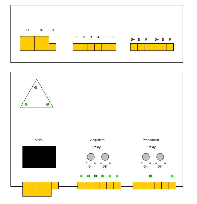
Standard power inputs, 6 R out, 2 or 6 (B+ B- R) for processors. I would like to see voltage displayed and have a status LED (green) on each of the 8 or 12 R outputs, wired in so they turn on only if there is a device successfully drawing current.
I would like to see delay adjustment, both on and off, for everything, rather than only on for the amps and only off for the processors. One set for the bank of R outputs, and separate ones for each pair of 'device' outputs (delay applied to the R terminal only, of course), so that the user (on the DD-66) would be able to have devices power up/down is a specific order if need be.
Example:
Amps: 5 sec on, 0 sec off
Devices 1 & 2: 2 sec on, 3 sec off
Devices 3 & 4: 0 sec on, 5 sec off
Devices 5 & 6: 1 sec on, 1 sec off
ON: Devices 3 & 4, Devices 5 & 6, Devices 1 & 2, Amps
OFF: Amps, Devices 5 & 6, Devices 1 & 2, Devices 3 & 4
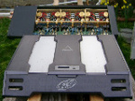
As for looks, It would be OK if it matched current PG amps, but I would also suggest doing it in such a way as to not have them look out of place when installed with different amps. As in, I'd love a white one to go with my MS amps.
Input (Both):
B+
B-
R
Output (DD-62):
6 x R
2 x B+
2 x B-
2 x R
Adjustments (DD-62):
2 x Delay On
2 x Delay Off
Display (DD-62):
8 x LED
Volts
Tri-LED status lights
Output (DD-66):
6 x R
6 x B+
6 x B-
6 x R
Adjustments (DD-66):
4 x Delay On
4 x Delay Off
Display (DD-66):
12 x LED
Volts
Tri-LED status lights
Here's a quick idea of what I'm thinking of for layout for the DD-62. Obviously the DD-66 would just be another 2 pair of processor outputs and delay adjustments. Volts display may look better in upper right corner, not sure...