Electric Supercharger, round three...

Any non-electronic/automotive related discussion goes here. Current events, sports, music, etc.
ydnap
More like Bannedy...
Posts: 1305
Joined: Thu Dec 07, 2006 2:05 pm
Location: Somewhere else :)

Electric Supercharger, round three...

Post by ydnap »

Before I start yes I know they're shit, and yes I know they don't do anything. Well, do they?

OK, after doing months and months of research (it all began last October but I kept it quiet) I have finally got a concept for one that WILL work and WILL produce boost.

It all began when TomOTEC and I bought some plans from the net. We didnt like the look of them because it was all a bit ghetto, and the fact you needed 3 car batteries wasnt that appealing either. And, at the end of it all you would end up with a pretty weak boost anyways.

However, in the months afterwards I *did* find one that provides a nice boost. Problem was it was $2000 lol.

Basically it's a centrifugal but powered by electricity. And it looks just like the front end of a turbo (minus the exhaust housing and wastegate.)

So I went on ebay and bought one of the plastic bilge pumps to give me an insight into what goes on, ended up blowing it up with 40 volts. It wouldnt have worked (and I knew this) because it was made from plastic and concaved when any pressure built. I did have fun blowing things accross the living room until a really bad burning smell came from the motor.. It was $25, the guy selling them only does so to stop people getting ripped off..

Anyway, time to bring you all up to speed. I decided a long time ago that I was going to see this through, and I was going to end up with something that could be ran electrically and pump air into my intake system. I have seen this being done with a leaf blower and it works. I dont want to argue over that, it was Dyno'd and proven.

Now this isnt going to be something anyone can run out and do, remember Im 33 years old and have a EXTREMELY technical background. If I dont know how something works I will get one and spend the day taking it apart to figure it out. By the end of the day I know *EXACTLY* what it does.

So I had put my project to one side recently because of everything else I have been doing on the car, but I still had all kinds of shit laying around my apartment ready for the project to kick back into action.

And then yesterday I got the call that has re-ignited the whole affair.. My friend Ryan (with the rather stupidly fast STI wagon) called me and said "dude, I got you a turbo to play with, come and get it"

Before anyone plays judge, jury and executioner remember this turbo was spent. All of the bearings had died and there was play in the impellor shaft. Using it as intended would have ended in tears. BUT.. It was all complete and therefore perfect because I didnt need any of that anyways.

So I got over to Ryan's yesterday and began learning what goes into a turbo, what it does and how it works.. Ryan said that they operate around the 25k-30k RPM range and provide a real strong boost there. So we set to taking it apart..

Before we did that however we rigged a 15,000 RPM angle grinder to the exhaust impellor and wound the turbo up. Nice boost of air circulating the garagge LMAO. (P.S DONT try this at home. Even the dust from the garage floor almost took skin of my legs.. We're talking danger here).

So now I knew what I was going to use for the 'motor'.. I have a grinder that produces 18k RPM that I bought to cut my seat brackets... It was $35 and has sat in the box since then. I'm no metalworker...

However, I can already hear the skeptics among us saying "dude, 18k RPM isnt enough" and they're absolutely right. And that's where my skill comes in...

The concept.

I have an immaculate turbo. All that was done on it were the internal bearings. The housing, impellor and parts I need for this are all there.

I also have an angle grinder motor, capable of 18k RPM.

Now, to make this bastard REALLY give off boost Im going to need to double the RPM output of that motor.. How? easy.

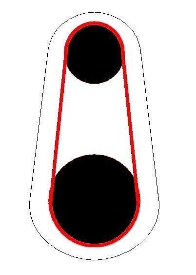
I have a back wheel from a mountain bike over @ my uncles, with a good chain. Bike was destroyed when I ran into a ditch and bent the front end, but it has what I need..

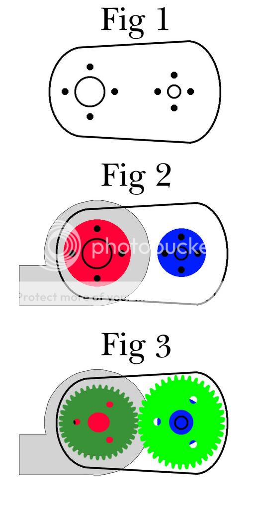
So here is what will sit on the back of the now modded turbo -

It's a steel plate with spindles on rollerskate bearings.. (well at the moment its a pic I made in paint). I studied ratios in school and I will be running 2:1. The drive gear will be twice the size of the gear on the spline of the turbo, making me spin around the 36000 RPM mark. And angle grinder motors are INCREDIBLY torquey too, theyre made to cut steel.

So the small gear will go down into the turbo, and the large gear will be on the grinder motor. And the red in the pic is a MTB chain.

Image

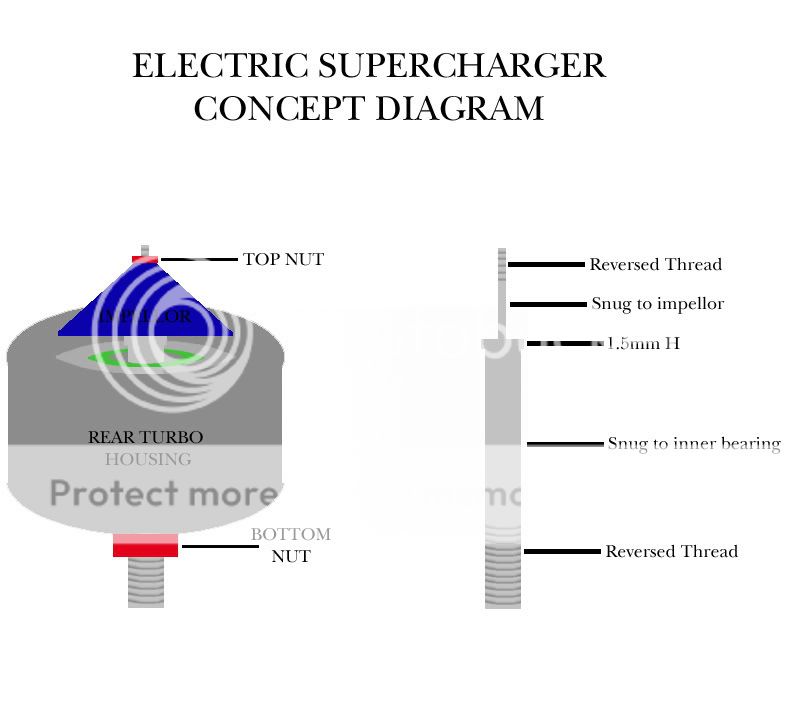
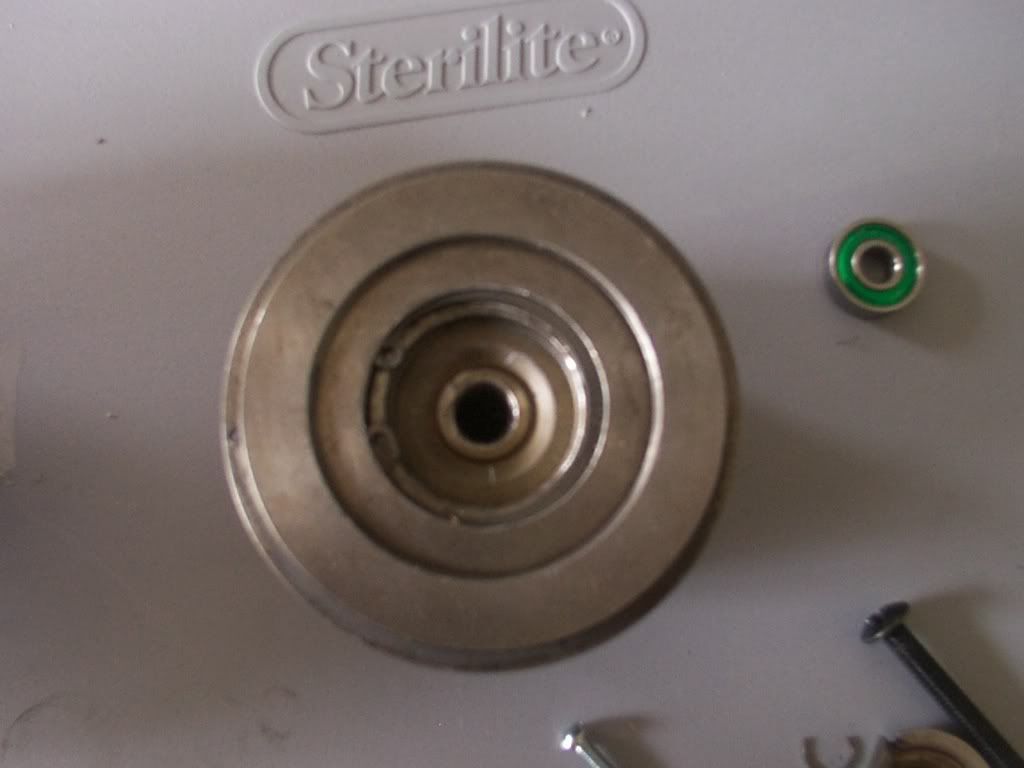
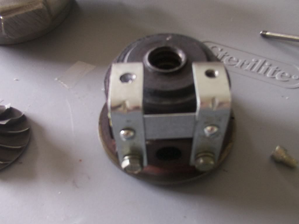
And now for what I have to do with the turbo.

This is the ass end of the rear assembly (Turbo is in 2 halves held together with a large spring clip.. This turbo comes from a MITSU)

The hole in the middle will be skimmed out to hold a rear bearing (also in the pic)

Image

There is a nice lip inside that will stop the bearing from falling in.

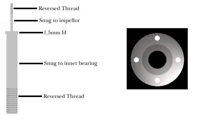
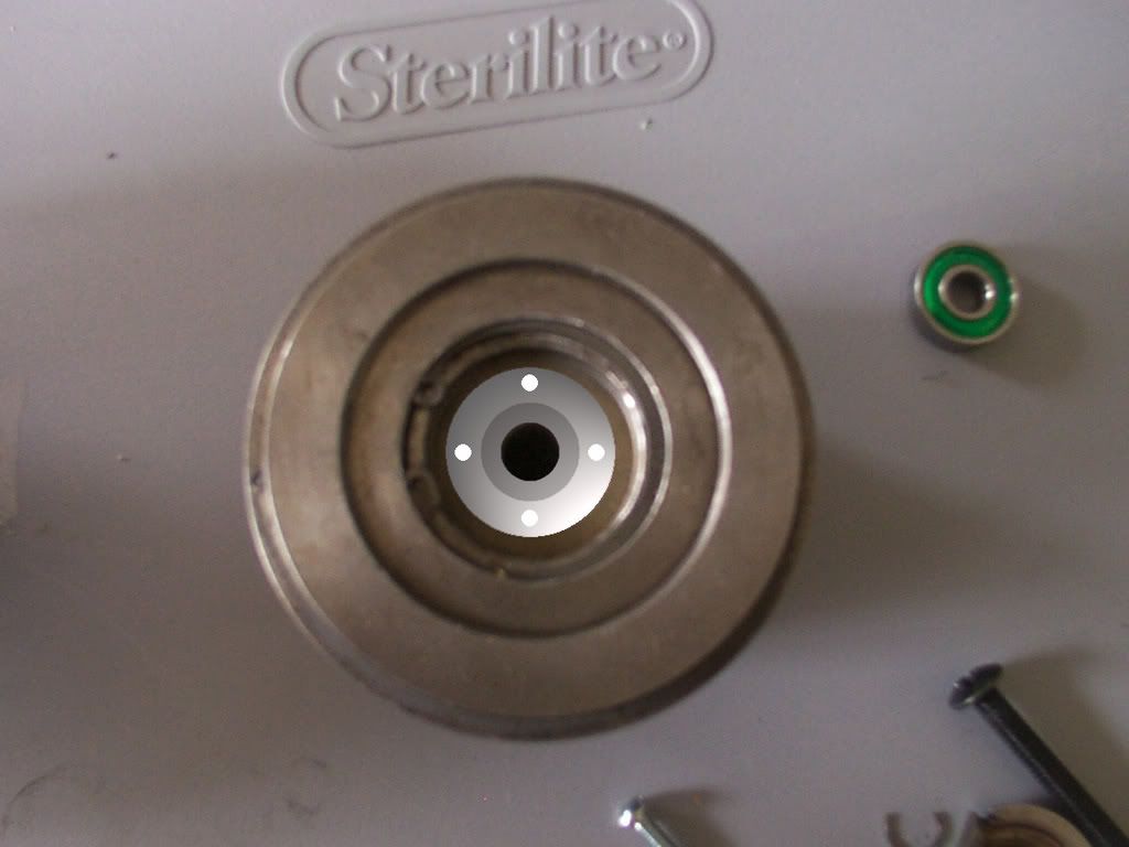
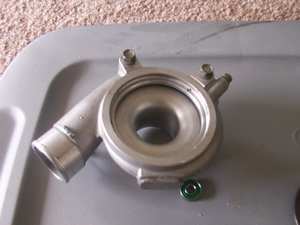
And now how the frontal bearing will be held in..

Here is the front end of the rear part of the turbo -

Image

And here is what I will be getting machined.. A bearing cup to hold said frontal bearing.
Image

And wehre it sits. 4 holes hold countersunk allen bolts holding it in, bearings press into center..

Image

Here is the worn and snapped spline from the old assembly -

Image

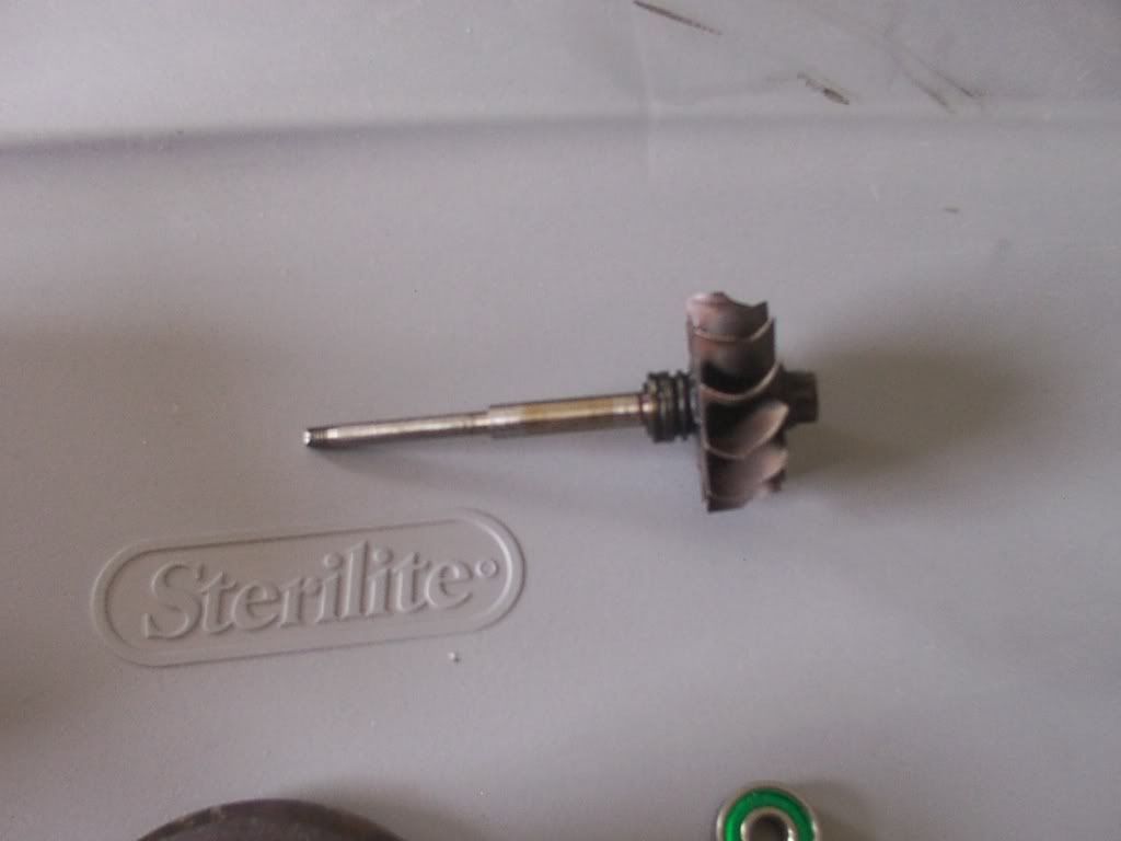
I will be getting one machined that fits snug into the rollerskate bearings (which are ceramic BTW, donated by the same guy who gave me the turbo) At the back end it will protrude out and be welded to the small gear. Front end it will taper in and the impellor will bolt on. It will ride snug inside the bearings, and spin really smooth.

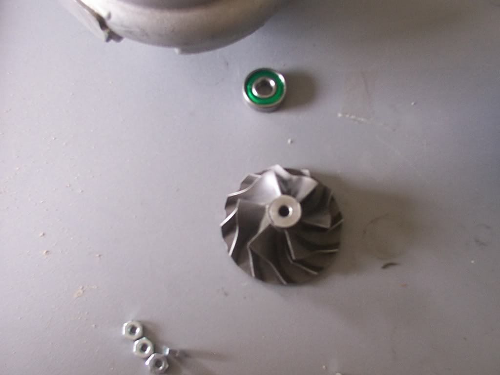
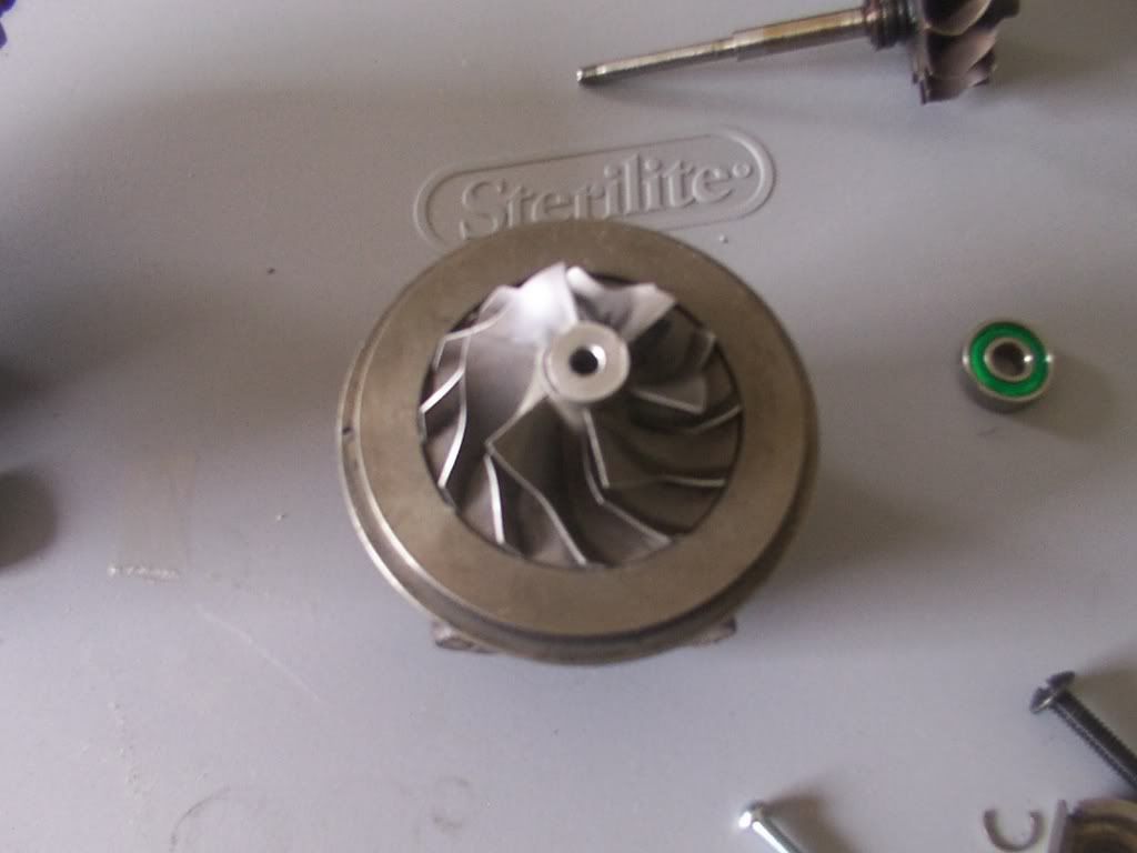
The impellor. This turbo is really well machined.. The diffuser is part of the body.. Thankfully the impellor isnt damaged and pretty much like brand new
Image

Top end of turbo -
Image

Where the impellor rides, 1.5 mm off this housing..

Image

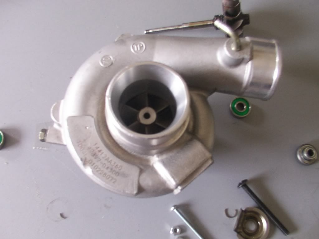
And what it looks like when assembled -
Image

Fabrication has begun and is going well, here is a part of the bracket assembly that will hold the gear/chain/motor assembly onto thr back of the tuebo, basically making it a centrifugal air pump.
Image


And I'll be off to the machine shop soon to get all the parts I need planned out and machined.

I will, of course, keep everyone updated :)

*Note* I wasnt entirely truthful about the whole thing as I would have gotten into shit with the moderators on the forum I visit. However, this bastard will work !
If you're going through hell keep going

Winston Churchill

"this is the world's most powerfulest high's amp."

Some dumb cunt.
ydnap
More like Bannedy...
Posts: 1305
Joined: Thu Dec 07, 2006 2:05 pm
Location: Somewhere else :)

Post by ydnap »

Ok I forgot to mention something.

Boost control.. At first we were worried that around 36,000 RPM this thing would only provide all out full boost. Im not even sure my injectors could keep up with that..

We were just about to be bummed out that there would be no control and I had a brainwave.. And, it's ingenious yet dirt cheap..

Inline stopcock. The same ones you use on a water main with the red bar that twists to turn the water on/off. It's basically nothing but a brass valve.

So let's say one end was bolted and soldered into the aluminum tube of the air intake, and the other end was fitted with one of them cute little breather filters (designed for cars). All I would need to do then to reduce the boost pressure is adjust the inline stopcock to let air in after the charger, reducing the boost pressure inside the CAI.

The very same way the valve on a pressure cooker works.

See, I told you I was smart :lol:
If you're going through hell keep going

Winston Churchill

"this is the world's most powerfulest high's amp."

Some dumb cunt.
VW337
Meatgician
Posts: 2780
Joined: Wed Dec 06, 2006 9:53 am
Location: PORK-Land OR

Post by VW337 »

For some reason I see traumatic injuries in the near future.........
I think we've established that "Ka Ka" and "Tukki Tukki" don't work.
ydnap
More like Bannedy...
Posts: 1305
Joined: Thu Dec 07, 2006 2:05 pm
Location: Somewhere else :)

Post by ydnap »

lol there will be a 1/8 outer casing over the gear unit with the chain in.

I said to Ryan yesterday "dude I know I aint leaving here without blood being spilt" but only ended up with a couple of really nasty pinches from the pliars :lol:

It'll work... Tom (OTEC) has access to a machine shop.. Same place I did all the work on the car.. They make water pumps for theme rides, wells and so on. So they machine parts all the time..

I need to get 2 spindles and 3 bearing housings machined, should be done in an evening..
If you're going through hell keep going

Winston Churchill

"this is the world's most powerfulest high's amp."

Some dumb cunt.
ydnap
More like Bannedy...
Posts: 1305
Joined: Thu Dec 07, 2006 2:05 pm
Location: Somewhere else :)

Post by ydnap »

To show how the rear end of the old turbo is being built I did a tech drawing. It's not great, but shows what's needed on the rear :)

Image

On the left is the unit itself.. Few things need esplaining there.

1. The bottom red bolt that holds it all together will not only bolt on but will also have a grub screw inside it that will lock it in place once it's adjusted. Just to make sure I dont end up with any play upward or downward on the spline.

2. As you can see from the right side pic there is a larger part of the spline that stops the impellor from moving downward and also sits in the upper bearing. So it'll go in from the front unlike before.

The trick part here though is that that stopper is also the elevation needed to put the impellor in it's position so it doesnt hit. I have gussed it roughly around the 1.5mm area, but this will all be measured using VERY precise measuring tools, to make sure that it's machined to perfection. I forget what theyre called now but theyre accurate to within 1/10th of a mm.

The thread on the rear end of the spline will allow me to bolt on the small gear that will be running from he motor on the motor assembly.. All the bearings will be greased, no indifferent to them being ran on a skateboard/skate/street luge.

But the pic is for a general idea of how the SC unit assmebly will go together, and to show I do have a plan lol :)
If you're going through hell keep going

Winston Churchill

"this is the world's most powerfulest high's amp."

Some dumb cunt.
User avatar
Mastiff
French Poodle
Posts: 1537
Joined: Wed Dec 06, 2006 7:44 pm
Location: earth
Contact:

Post by Mastiff »

You do realize you are 100% obligated to video the first start up run when GOD gets angry with you and you all die a very Darwin’esk form a death. :P


good luck man and do try to be carful.
ydnap
More like Bannedy...
Posts: 1305
Joined: Thu Dec 07, 2006 2:05 pm
Location: Somewhere else :)

Post by ydnap »

Thankfully any parts that are critical to it being safe are being machined, so everything should be pretty good from a hold together standpoint.

The bracket I have fabricated will be welded (bolts onto the centre strut) as I have a pal of mine who can weld. The 'pan' that will hold the motor/gear/chain assembly will be 1/4" steel or thicker aluminum, and will have a bolt on cover made from 1/8 steel. Well greased too lol.. That will weld onto the brackets so the 3 bolts in the lower turbo assembly will be cranked to hold it on tight..


The bolts holding the drive splines in will be cross drilled and will have locking grubscrews to stop them loosening, so other than that I cant see anything going majorly wrong providing the drive train is perfectly centred.. The bearings are ceramic, pal of mine is a serious skater and has loads of them (hes also loaded, same dude that handed over the turbo to be taken apart)

If anything it will be seriously overbuilt.. I mean a MTB chain and sprockets have held my ass when I was heavy (195 lbs) accelerating in 14th gear, so I know theyre up to staying together.. plus the chain will be short giving it even more strength..

Only bitch part is hoping TomOTEC can be allowed to use the mill, without the machined parts Im dead in the water..

Don't suppose any of you here know someone who can make the parts I need? I can send the old spline and bearings so that everything would be the right size/fitting.
If you're going through hell keep going

Winston Churchill

"this is the world's most powerfulest high's amp."

Some dumb cunt.
ydnap
More like Bannedy...
Posts: 1305
Joined: Thu Dec 07, 2006 2:05 pm
Location: Somewhere else :)

Post by ydnap »

If you're going through hell keep going

Winston Churchill

"this is the world's most powerfulest high's amp."

Some dumb cunt.
ydnap
More like Bannedy...
Posts: 1305
Joined: Thu Dec 07, 2006 2:05 pm
Location: Somewhere else :)

Post by ydnap »

Fuck me lmao !

Holy shit on a stick batman !!!

http://www.turbomagazine.com/tech/0406t ... index.html


Our completely stock Nissan Altima four-cylinder outfitted with an automatic transmission jumped from 105 whp to 184 whp with the ESC-400 at only 5 psi boost.

I'll settle for 2 lbs of boost haha
If you're going through hell keep going

Winston Churchill

"this is the world's most powerfulest high's amp."

Some dumb cunt.
rlockwood
Posts: 344
Joined: Sun Jan 21, 2007 10:14 am

Post by rlockwood »

how much do you expect to pay to have the new impellor machined?

was the old one even machined? looks like the fins were tig'd.

that sort of machining isnt anything I have particular experience in, besides reading a few articles (mostly related to jet engine impellors, but same concept :P)

all I can say is, 5th axis machining is SPENDY
I'm afraid of widths.
ydnap
More like Bannedy...
Posts: 1305
Joined: Thu Dec 07, 2006 2:05 pm
Location: Somewhere else :)

Post by ydnap »

I dont need an impellor, I have one :) I need a shaft to connect it to and sit in the bearings.. And a bearing cup of course.

Other than that I dont need anythign else machined, I took the angle grinder to bits a minute ago and realised I can bolt the drive sprocket straight to the threaded outlet shaft on it.

I was going to run it into bearings and so on, but it's alot easier to just bolt the sprocket on there directly :)

So all I need is 2 machined parts, the rest I have (apart from the steel plate that holds it all together and that doesnt need to be particularly pretty) and the inverter, and a 10 amp 2500 watt inverter is $79 and has it's own cooling fans :)
If you're going through hell keep going

Winston Churchill

"this is the world's most powerfulest high's amp."

Some dumb cunt.
ydnap
More like Bannedy...
Posts: 1305
Joined: Thu Dec 07, 2006 2:05 pm
Location: Somewhere else :)

Post by ydnap »

I'm not that sure about machining as it goes.. but, I would imagine that both of the parts I need can be made from steel bar and would be made on something that looks like a wood lathe..

Here are the parts I need (well very rougly of course, but itll give you an idea of what they look like at least)

Image
If you're going through hell keep going

Winston Churchill

"this is the world's most powerfulest high's amp."

Some dumb cunt.
User avatar
Mastiff
French Poodle
Posts: 1537
Joined: Wed Dec 06, 2006 7:44 pm
Location: earth
Contact:

Post by Mastiff »

pandy I have two words you need to read up on ….. Dynamic balancing
VW337
Meatgician
Posts: 2780
Joined: Wed Dec 06, 2006 9:53 am
Location: PORK-Land OR

Post by VW337 »

Okay before you kill yourself Pandy I suggest using a chain stronger than one made for a mountain bike. There is a reason why V8's ditch a timing chain when they start climbing into the 9K RPM range. It will stretch and end up being a very devastating grenade shrapnel device or sorts.


When something starts spinning at High RPM any and all minor flaws become real big flaws, this is why tires are rated for certain speeds as are wheels, cranks, cams etc......


If the parts you are machining are not 100% tested harmonically and any other way you can think of you are looking at flying bits going everywhere.


Please do me a favor and calculate the mass of a bullet and the muzzle velocity and think about the things it will penetrate, then think about the weight of a chain link and approximate the speed it will be spinning at.
I think we've established that "Ka Ka" and "Tukki Tukki" don't work.
ydnap
More like Bannedy...
Posts: 1305
Joined: Thu Dec 07, 2006 2:05 pm
Location: Somewhere else :)

Post by ydnap »

There will be a 1/8 steel covering over the assembly..
If you're going through hell keep going

Winston Churchill

"this is the world's most powerfulest high's amp."

Some dumb cunt.
User avatar
Mastiff
French Poodle
Posts: 1537
Joined: Wed Dec 06, 2006 7:44 pm
Location: earth
Contact:

Post by Mastiff »

Image
User avatar
stipud
Voltage Ohms
Posts: 14719
Joined: Sat Nov 26, 1983 4:00 am
Location: Burnaby, BC
Contact:

Post by stipud »

So.... why don't you just rebuild the turbo and install it properly?

Also... yay for TD04. Same turbo they have on the Saab 9-5 Aeros. Those things are omega reliable and good for over 20psi.
ydnap
More like Bannedy...
Posts: 1305
Joined: Thu Dec 07, 2006 2:05 pm
Location: Somewhere else :)

Post by ydnap »

To rebuild it would have required special tools, an intercooler (because of the exhaust gases) and oil lines and so on. Money, basically.

And with a Turbo because of the way it recycles the gas and pressure there's a lag.

Electric superchargers offer a reasonable boost with no lag and it doesnt cost you anything from your HP to generate.
If you're going through hell keep going

Winston Churchill

"this is the world's most powerfulest high's amp."

Some dumb cunt.
VW337
Meatgician
Posts: 2780
Joined: Wed Dec 06, 2006 9:53 am
Location: PORK-Land OR

Post by VW337 »

Wrong Pandy.


The more current draw your alternator is demanded to compensate for the less freely it spins, so it will become a HP drain in the process of creating said HP. There is no such thing as free power.
I think we've established that "Ka Ka" and "Tukki Tukki" don't work.
User avatar
Bfowler
Briaans..... BRIAAAAANNNNNNS
Posts: 10769
Joined: Wed Dec 06, 2006 11:06 am
Location: So easy, a cavewomen could do him

Post by Bfowler »

law of thermodynamics > all.

(so much so that i actually have an embroidered/ cross stitch of that quote in my house)
my ex-girlfriend said "its car audio or me"
i've had tougher choices at a soda machine...
ydnap
More like Bannedy...
Posts: 1305
Joined: Thu Dec 07, 2006 2:05 pm
Location: Somewhere else :)

Post by ydnap »

I see Errin... Well I pretty much only have to put out about another $100 on this to get it done and installed (most for a inverter, but I can use that for my gamecube also.. I wont run them both at the same time however :) )

As for the concerns over it being dangerous? I have taken it all into consideration. And if anything I am over building it..

Things considered were -

1. Will it get too hot?

It'll get hot no doubt, but bear this in mind..

There are no hot gases at play here, so all it is is a angle grinder (complete) turning a chain that turns a spindle with a billet impellor on it.

It wont be on all the time, only at certain RPM ranges or certain places in the throttle. It's going to be a very quick boost, 3-4 seconds at a time, then off again. Unlike a turbo or belt driven SC it doesnt need to be on all the time. It doesnt need to 'wind up' itll be pretty much instantaneous.

The bearings are ceramic. These are the same one my buddy (who is a 200lb fatass) uses for skating on, and he is a pretty extreme skater.

Theyre not taking any weight and are built to be abused (same ones used by street luger's and they do in excess of 60 mph with 160lb over them).

It's sucking nothing but cold air.

2. Will it be 'balanced'?

Yes. Any part that needs to be perfectly weighted and balanced will be machined to within 1/10 of a mm. The grinder itself is a complete, balanced unit. the spline that connects to the drive gear comes out of the grinder and is perfectly level and centered, and the spline going through the bearings and onto the impellor will be machined.

The drive cogs? very simple. Once removed from the 'clump' (mountain bike gears all seperate) they will have billet discs cut using a hole cutter, which will put a perfectly centred hole inside a perfectly centered circle. These will be measured to within 1/10 of a mm and then welded to the gears, slotting over the drive splines.

The design is being kept stunningly simple. For a reason.

I will regrease and replace all the bearings with each oil change (3000 miles) and I will also have the ability to completely turn it off when I dont want to use it (and I wont use it all the time as itll cost me more gas. Bit dumb to have it on for a 2 mile drive to work)

It'll also be bench tested and left to run for an hour or so before it even gets a whiff of my engine bay, once the test is complete Ill take it apart and have a look to see what kind of fatigue (if any) it has endured.

As for your concerns over the chain snapping Errin? Im not worried. I dont think that will be a problem, and here's why...

I have ridden my mountain bike up hills when I weighed 200 pounds, using 14th gear standing up with my full weight on the pedals. The chain didnt snap. I have also ridden it at over 30 mph in the standing position with my full weight in 21st gear. Still no snap.

The part it is driving is uber light, and sits in very fast ceramic bearings. There will be hardly any strain when it bites up and itll get it moving very quicky. However, in the event of a failure the chain guard cover is also being over built using 1/8 steel sheet. chain guards on bikes are alot thinner.

Also after you mentioning chain problems I came up with another good idea, from my BMX days.... ICT's (chain tensioners) that will clip to the edge of the steel plate that holds the motor and turbo together, and anchor into the bolts that the grinder uses to bolt into the plate.. They will be left loose, chain put on and then the tensioers cranked to pull the grinder away from the turbo, tensioning the chain. At that time the bolts holding the grinder to the plate can be tightened :)
If you're going through hell keep going

Winston Churchill

"this is the world's most powerfulest high's amp."

Some dumb cunt.
rlockwood
Posts: 344
Joined: Sun Jan 21, 2007 10:14 am

Post by rlockwood »

not going to get into it, but there are way too many flaws in your logic (and the logic of the entire project) for me to offer any advice on..

you have to look at where the energy is coming from.

the first thing you should consider is...

a typical turbo is effective because exhaust gasses that would otherwise be wasted are recycled and used for more power.

also.. 1/10 of a millimeter = .0003" assuming you mean +/- that for a tolerance. Realize this is quite tight and would need to be ground.

good luck with the skateboard bearings and mountain bike chain.

(for reference, ive built many machine spindles that run upwards of 10,000RPMS 40+ hours a week)
I'm afraid of widths.
User avatar
stipud
Voltage Ohms
Posts: 14719
Joined: Sat Nov 26, 1983 4:00 am
Location: Burnaby, BC
Contact:

Post by stipud »

The TD04 is one of the easiest turbos to rebuild. It only costs a few hundred to get it done right at a shop. Intercooler? I will give you one for the cost of shipping.

Pandy did you read that article you posted above? The guy who made that turbocharger already tried your exact method in many different ways and it was never really successful. It's not until he switched to an Eaton supercharger that it began to work.
ydnap
More like Bannedy...
Posts: 1305
Joined: Thu Dec 07, 2006 2:05 pm
Location: Somewhere else :)

Post by ydnap »

Still talking over plans and ideas. Have scrapped the grinder deal because of the fact that the motor is part of the grinder so I would have to use it all. Instead I am using a 1200w shop vac motor.

Also the chain idea has been scrapped for a lexan 'gearbox' made from 4 pieces of 1/4" lexan. One solid one for the bottom with the motor and turbo mounted with the 2 splines (motor and turbo) going into the 'box' then 2 sides cut as frames and epoxyed down, then a solid one for the top. Will make gaskets from those high heat cooking sheets (the new rubber ones) and fill it with trans fluid. I am also using carbon steel gears to drive it instead of sprockets and a chain, these gears will be 40 tooth and a 18 tooth for the 2:1 ratio. 1200w vacuum motor does about 15k rpm and theyre real strong too.. They used them in mythbusters to power a hovercraft (well Adam did..) They also produce alot of air lol, Adam got his lip sucked into one and it ripped a chunk out of his lip lol...

And here is how it will work.. This doesnt show the complete built up gearbox, just the bottom plate, but you can see how it will work on the turbo. Itll also be alot cleaner and lighter and better than the sprocket and chain idea, and stronger and safer too.

Image
If you're going through hell keep going

Winston Churchill

"this is the world's most powerfulest high's amp."

Some dumb cunt.
ydnap
More like Bannedy...
Posts: 1305
Joined: Thu Dec 07, 2006 2:05 pm
Location: Somewhere else :)

Post by ydnap »

We also figured out a better and MUCH easier way to make the spline for the turbo. Instead of getting a piece of bar machined we are going to use a 5/16 bar (inner bearing size) and drill into the top, then use a bolt that bolts into the spline to hold the impellor on. This can be done with a drillpress instead of having to get parts machined which would cost a bomb.
If you're going through hell keep going

Winston Churchill

"this is the world's most powerfulest high's amp."

Some dumb cunt.
Post Reply