Has anyone had madisound custom build you crossovers?

Need help with your car stereo system? Have a technical question? Post here.
User avatar
shawn k
Posts: 757
Joined: Thu Apr 01, 2010 2:33 pm
Location: Maine

Re: Has anyone had madisound custom build you crossovers?

Post by shawn k »

Eric D wrote:
*****

I measured people’s systems at the level they listen to them at (most of which was full volume). With music signals, the signals would clip at the limits of the amplifier’s outputs.

Instead of just discrediting a test I performed, why not mention one you did?.
I wasn't trying to discredit your test. I just find it silly that "every" system you measured was clipping all the time! I mean that's seriously hilarious!

*****
Eric D wrote:Wow, I used an amplifier onboard crossover in an obviously failed attempt to explain to you the differences between a symmetrical and asymmetrical crossover. This has been like the third attempt I have made, and you still don’t know the difference. I never said anyone is forced to use the onboard crossover for an active system (although they have every right to if they wish)
I know differences!! And I certainly don't need YOU to explain anything to me :roll: I was simply trying to clarify a few points in order to stay on track, which I see obviously didn't work for you :(

*****
Eric D wrote:You actually have now claimed that the driver and passenger side speakers will have the exact same frequency response, and all that is different is a phase shift? So in other words the car itself has no affect on the response? This does not make any sense to me. There is a lot more going on than just a simple phase shift.
Umm.. phase shifting is not a "simple" matter :?

*****
AKA "THE HATER"
User avatar
Eric D
Short Bus Driver
Posts: 4259
Joined: Sat Dec 30, 2006 8:50 am

Re: Has anyone had madisound custom build you crossovers?

Post by Eric D »

In my town there are not a lot of examples of "high end" audio, so I don't find it silly they were all clipping. Sadly it is probably why all the car audio shops but one died in this town.

If you really know the differences why don't you seem to with your text? You seem confused.

Phase shifting is a lot simpler than altering frequency response. Try it sometime, you will see what I mean.
Got "schooled" by member shawn k on May 10th, 2011...
No longer really "in tune" with the audio industry, and probably have not been for some time.
Hands down the forum's most ignorant member...
Don't even know what Ohm's law is...
User avatar
Eric D
Short Bus Driver
Posts: 4259
Joined: Sat Dec 30, 2006 8:50 am

Re: Has anyone had madisound custom build you crossovers?

Post by Eric D »

Since this thread has now gone full circle, we can get back to the original point Shawn made, which I disagree with...
But Mackenzie stated he wanted "efficient" and running passive xovers is not an efficient solution..... just saying.
Although there might be time when an active crossover is more efficient than a passive, this is rarely the case...

Thanks to Shawn for reminding me of this test I performed several years ago...

Image

Yes, this is just one example, but it is better than nothing.

From that graph one can see that between 20Hz, and about 1kHz there is “virtually” no loss of voltage at the terminals to the midrange (within 1db)

From 15kHz to 30kHz, the tweeter actually is at a higher input voltage than that of the crossover with two pad settings, and the same with one. This is an example of the “resonance” I mentioned earlier in this thread. The tweeter is actually getting more voltage than what is coming from the amplifier, due to the interaction of the crossover.

So, Mackenzie, going with a passive crossover is going to be efficient, and I am personally wiling to bet that if you invest the time and effort into tweaking one, you will be very pleased with the results (and pleased with your accomplishment).
Got "schooled" by member shawn k on May 10th, 2011...
No longer really "in tune" with the audio industry, and probably have not been for some time.
Hands down the forum's most ignorant member...
Don't even know what Ohm's law is...
User avatar
shawn k
Posts: 757
Joined: Thu Apr 01, 2010 2:33 pm
Location: Maine

Re: Has anyone had madisound custom build you crossovers?

Post by shawn k »

Eric,

Please explain this graph to me.
AKA "THE HATER"
Mackenzie
Where all da white women at?
Posts: 1524
Joined: Wed Dec 06, 2006 12:17 pm

Re: Has anyone had madisound custom build you crossovers?

Post by Mackenzie »

Hmm, well anywho, Im just gunna pick up a different component set that can take more abuse, and is efficient. It would be ideal to run some type of pa type speaker/ tweet, but I wont have the processing power/ equipment. Im still on the search for some efficient, good sounding comp sets, but I may have narrowed it down a bit now. Maybe one day I will go active, but its too much extra right now. If I still had my pioneer 880 prs deck, I would give it a shot, but since I no longer own one, then I will pass. I never should have let go of my 880.. O well, let the component set search continue. This is going to be one of my larger systems, so efficiency is key.
ttocs
the Floor Sweeping Hack with Golden Ears
Posts: 14797
Joined: Fri Dec 19, 2008 9:53 pm

Re: Has anyone had madisound custom build you crossovers?

Post by ttocs »

I have a super nice set of diamond audio hex series three ways for sale for $300 plus shipping if you don't mind buying 2nd hand gear. I had them bi-amped on a D9 800.4 and am only hoping the Ti elites sound as good as these did. PM me if your interested, the 6's were in an eclosure in my door safe from moisture and the 4 and 1 were behind grills in the kicks. So again they were kept dry and safe.
what else can I say I am a grumpy asshole most of the time.
User avatar
Eric D
Short Bus Driver
Posts: 4259
Joined: Sat Dec 30, 2006 8:50 am

Re: Has anyone had madisound custom build you crossovers?

Post by Eric D »

shawn k wrote:Eric,

Please explain this graph to me.
Sure, what part do you need clarification on?

Does it make sense to start a different thread on this?
Got "schooled" by member shawn k on May 10th, 2011...
No longer really "in tune" with the audio industry, and probably have not been for some time.
Hands down the forum's most ignorant member...
Don't even know what Ohm's law is...
User avatar
shawn k
Posts: 757
Joined: Thu Apr 01, 2010 2:33 pm
Location: Maine

Re: Has anyone had madisound custom build you crossovers?

Post by shawn k »

Eric D wrote:
shawn k wrote:Eric,

Please explain this graph to me.
Sure, what part do you need clarification on?

Does it make sense to start a different thread on this?
No need for a new thread. Just a general outline for what this graph is displaying would be fine
AKA "THE HATER"
User avatar
Eric D
Short Bus Driver
Posts: 4259
Joined: Sat Dec 30, 2006 8:50 am

Re: Has anyone had madisound custom build you crossovers?

Post by Eric D »

The graph is voltage vs frequency, measured at the terminals to the speakers in a passive network. In this case the Boston Z6.

This is voltage (RMS) vs frequency, not SPL vs frequency, so it is a measure of electrical voltage, not acoustic output.

This is pretty much identical to measuring the frequency response of an amplifier.
Got "schooled" by member shawn k on May 10th, 2011...
No longer really "in tune" with the audio industry, and probably have not been for some time.
Hands down the forum's most ignorant member...
Don't even know what Ohm's law is...
ttocs
the Floor Sweeping Hack with Golden Ears
Posts: 14797
Joined: Fri Dec 19, 2008 9:53 pm

Re: Has anyone had madisound custom build you crossovers?

Post by ttocs »

in a perfect world that graph would be perfectly flat in the listening levels that we hear.
what else can I say I am a grumpy asshole most of the time.
User avatar
Eric D
Short Bus Driver
Posts: 4259
Joined: Sat Dec 30, 2006 8:50 am

Re: Has anyone had madisound custom build you crossovers?

Post by Eric D »

ttocs wrote:in a perfect world that graph would be perfectly flat in the listening levels that we hear.
Even in a perfect world this graph would not be flat. The voltages shown represent the response of the crossover. If we had a flat curve for either the tweeter or the midrange, we would have a short in our crossover, and the crossover would not be affecting the signal.

We can get a lot of information from a graph like this. From it we can see the slope of the low pass filter, the slope of the high pass filter, if the tweeter attenuation is reducing output by the value specified, and a lot of other useful info. For example, notice how there are two distinct slopes on the tweeter. This crossover has an additional filter circuit connected to the tweeter. Also notice how when the crossover set to SQ2 there is a bunch of wild stuff going on with the midrange. Placing this crossover in the SQ2 mode (a switch on the board) places a notch filter in with the mid, and adds a high pass as well.

As far as passive crossovers go, this one is more complex than most.
Got "schooled" by member shawn k on May 10th, 2011...
No longer really "in tune" with the audio industry, and probably have not been for some time.
Hands down the forum's most ignorant member...
Don't even know what Ohm's law is...
User avatar
Eric D
Short Bus Driver
Posts: 4259
Joined: Sat Dec 30, 2006 8:50 am

Re: Has anyone had madisound custom build you crossovers?

Post by Eric D »

Maybe this graph will make more sense...

Image

That is the response of my AX204a crossover. With 1V of input it yields the output show on the graph. Changing the internal modules will move the curve up or down in frequency.
Got "schooled" by member shawn k on May 10th, 2011...
No longer really "in tune" with the audio industry, and probably have not been for some time.
Hands down the forum's most ignorant member...
Don't even know what Ohm's law is...
User avatar
shawn k
Posts: 757
Joined: Thu Apr 01, 2010 2:33 pm
Location: Maine

Re: Has anyone had madisound custom build you crossovers?

Post by shawn k »

ttocs wrote:in a perfect world that graph would be perfectly flat in the listening levels that we hear.
Yes exactly!! And that's exactly what an "active" xover will give you. Hence the nice and flat response of this last graph that Eric has provided of the AX204.

Eric, I'm not sure why you would even post this latest graph, it only proves even more the benefits of an active filter compared to a passive one. Furthermore, thanks for the quick explaination of the first graph for the Boston Passive xover. I did NOT need "clarification" however. I wanted to be clear that YOU actually knew what the graph represented. As I had said on the older thread, this graph is only a representation of the response curve. This is done with EXTREMELY small voltage applied!!! The graph is measured via dBm. 1 dBm is equal to approximately 1 milliwatt! This graph is something that would be used for quality control or prototyping or something along those lines. It is absolutely NOT indicative of how it will perform in the real world when power levels will be "thousands" of times greater!!! :roll:

I worked on a little something this morning that should (hopefully) shed some light on the subject. It should be pretty clear to see that the crossover network does indeed rob power.

Please give me a little bit to get the pics and info organized.
AKA "THE HATER"
User avatar
Eric D
Short Bus Driver
Posts: 4259
Joined: Sat Dec 30, 2006 8:50 am

Re: Has anyone had madisound custom build you crossovers?

Post by Eric D »

Where are you getting 1 milliwatt from?

The first graph was done at 2V, or 1W for a 4 ohm load.

If you think these graphs show anything related to an active crossover being better, you obviously don't understand the graphs.
Got "schooled" by member shawn k on May 10th, 2011...
No longer really "in tune" with the audio industry, and probably have not been for some time.
Hands down the forum's most ignorant member...
Don't even know what Ohm's law is...
User avatar
shawn k
Posts: 757
Joined: Thu Apr 01, 2010 2:33 pm
Location: Maine

Re: Has anyone had madisound custom build you crossovers?

Post by shawn k »

Eric D wrote:Where are you getting 1 milliwatt from?

The first graph was done at 2V, or 1W for a 4 ohm load..
There is very little information with this graph, all I can go by is what is given. Horizontal plane = freq. & Vertical plane = dBm...... and 1dBm = ~1mw

If 2v were in fact applied to the circuit in this graph, then the graph itself doesn't make any sense.
Eric D wrote:If you think these graphs show anything related to an active crossover being better, you obviously don't understand the graphs.
I don't see how it doesn't! Simply compare the freq response from the two graphs. The active xover has a smooth & nearly ruler flat response, where as the passive does not (even without the "SQ" circuit engaged)
AKA "THE HATER"
User avatar
Eric D
Short Bus Driver
Posts: 4259
Joined: Sat Dec 30, 2006 8:50 am

Re: Has anyone had madisound custom build you crossovers?

Post by Eric D »

Ever hear of a "scaling factor"?

In both graphs a scaling factor was applied to "normalize" the data at 0db. It just makes it easier to read. One can look at a frequency and see how far down it is instantly, instead of having to do any math to figure out how far it is down from the reference.

The passive crossover graph is not supposed to be ruler flat. That would defeat the whole point. The additional filters Boston used are EQing which contours the sound. This is actually a desirable result, not some mistake in the design. It is intentional.
Got "schooled" by member shawn k on May 10th, 2011...
No longer really "in tune" with the audio industry, and probably have not been for some time.
Hands down the forum's most ignorant member...
Don't even know what Ohm's law is...
User avatar
shawn k
Posts: 757
Joined: Thu Apr 01, 2010 2:33 pm
Location: Maine

Re: Has anyone had madisound custom build you crossovers?

Post by shawn k »

Eric D wrote:Ever hear of a "scaling factor"?

In both graphs a scaling factor was applied to "normalize" the data at 0db. It just makes it easier to read. One can look at a frequency and see how far down it is instantly, instead of having to do any math to figure out how far it is down from the reference.

The passive crossover graph is not supposed to be ruler flat. That would defeat the whole point. The additional filters Boston used are EQing which contours the sound. This is actually a desirable result, not some mistake in the design. It is intentional.
Fair enough. But that also makes the graph useless for the discussion @ hand (are passive xovers less efficient/ do they disipate power).

Think about it...... This graph is "scaled" down, which also means that any loss in voltage can be disregarded in order to show a "reference" level. For example... "if" the xover had an average 1v loss of energy that was disipated by heat, this could be ignored by simply "scaling" the graph to a 0db (below the 1v drop) reference point. It doesn't mean that the voltage was never lost!

I would be intersted to see what the graph "actually" lookse like with the appropriate peramters and NOT scaled! If 2v were indeed applied to the circuit, I would like to see this graph as true Voltage (unreferenced) vs Freq response. I'm more than confident that the entire freq response would now be "below" 2v, therefore indicating a voltage drop (loss in power) :?
AKA "THE HATER"
User avatar
Eric D
Short Bus Driver
Posts: 4259
Joined: Sat Dec 30, 2006 8:50 am

Re: Has anyone had madisound custom build you crossovers?

Post by Eric D »

I scaled the graph so at 2V you have 0dbm.

I played a 2V tone out of the amplifier (using the LMS output to drive the amp), and then adjusted the vertical scaling of the graph until it was at 0dbm.

Looking back at this I should have run another sweep of just the amplifiers output. But, I did this in 2002. It is not like I planed ahead to use this data in an online argument almost a decade later...
Got "schooled" by member shawn k on May 10th, 2011...
No longer really "in tune" with the audio industry, and probably have not been for some time.
Hands down the forum's most ignorant member...
Don't even know what Ohm's law is...
User avatar
Eric D
Short Bus Driver
Posts: 4259
Joined: Sat Dec 30, 2006 8:50 am

Re: Has anyone had madisound custom build you crossovers?

Post by Eric D »

If it is going to benefit this discussion, I will re run this test. I have all the equipment to do so.

But, I want specifics as to what needs to be tested. It takes a long time for me to dig up and setup all this equipment, the last thing I want is to have to do it all over again once completed.
Got "schooled" by member shawn k on May 10th, 2011...
No longer really "in tune" with the audio industry, and probably have not been for some time.
Hands down the forum's most ignorant member...
Don't even know what Ohm's law is...
User avatar
shawn k
Posts: 757
Joined: Thu Apr 01, 2010 2:33 pm
Location: Maine

Re: Has anyone had madisound custom build you crossovers?

Post by shawn k »

Ok, I did this little experiment quite a while ago with a set of Ti elites for my own purposes. I never documented the findings, so this time around I am. I no longer have the Ti elite's, but I do have a fairly descent xover here from PPI that will do the trick. The results of the test are similar to the findings I had back with the Ti elite's which only further reinforces that passive xovers do indeed rob power from the amplifier. Please know that I did not sabotage the findings in anyway!!! I'm not that kind of guy!

Here's the rundown:

I wanted to make this as simple as possible in order for anyone with an amp, a load (speaker or power resistor)& passive xover of course, a signal generator (cd player for instance), and a mulitmeter (or even just an ac volt meter) could perform this test for themselves.

For my particular test, I used a Kicker ZR240 amp to first drive a 4 ohm 100w resistor and then drive the same resistor with the xover inline to determine if the voltage would stay the same, or if the xover created a voltage drop. Also, the power applied was never higher than roughly 50'ish watts. This is well within the limits of the xover and should negate any dispute that the xover was working into saturation.

Note: I decided to use a power resistor instead of an actual speaker simply because it makes the measurements easier to read. The reactive load of a driver will make the measurements fluctuate at least to some extent and only makes it more difficult for "consistant" measurements. Please know I only did this for simplicity and the results are just as valid for resistors as they are for speakers :wink:

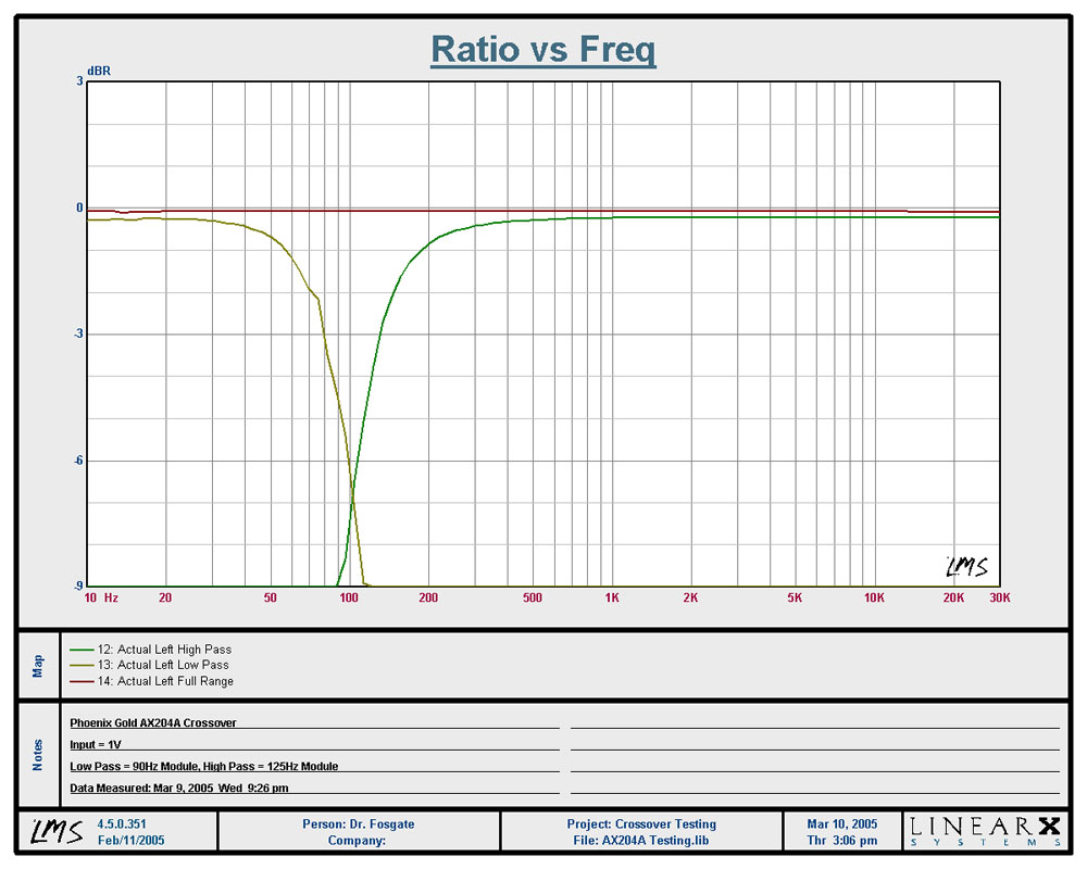
The resistor was connected to the "low" output of the passive xover. For this test I only used the "low" output from the xover. Again, to keep this as simple as possible. This particular xover is a relatively simple 12db/octave design using quality parts. The xover point is roughly 3khz and there are no other notch filters or inline resistors to impede the testing. Again.. simple. The amplifier was fed with a 100hz sinewave from the cd player (using a disc with test tones of course) that I use for bench testing product. I chose this particular freq for a couple of reasons. First, 100hz is FAR from the xover point. Meaning, in an ideal world, there should not be any voltage drop at the load due to the xover. Second, 100hz is definitely within the midbass region where "most" of us want every last bit of power we can get our hands on.

I decided to do three different power levels and determine just how much voltage drop (if any) was caused from the xover. The measurements are very easy to accomplish:

First: Apply the resistor directly to the output of the amplifer. Turn on the amp, feed it the 100hz signal, and record the AC voltage either at the output terminals, or the connecting points for the resistor istelf. Polarity is not an issue here sinse we are measuring AC. For my measurements, I gained the amp for nice even figures...5v, 10v, & 15v, but this is not necessary. THIS AC measurement is your reference point!!! The next step is to disconnect the resistor and now apply it to the "low" output terminal of the xover. Now, of course, you connect the xover "input" terminal to the amp just as if you were doing an install. Here's where you will find your results: Your next measurement is going to be the AC voltage "after" the xover. In other words, measure AC @ the output terminals of the xover. If your AC voltage is Identical to your prior "Reference" measurement, then the xover is NOT waisting power. However, if the the AC voltage is "any" lower than your prior Reference voltage, then the xover IS disipating power.

Here are my results:

First @ 5 volt AC..... the amp is driving the resistor directly

Image

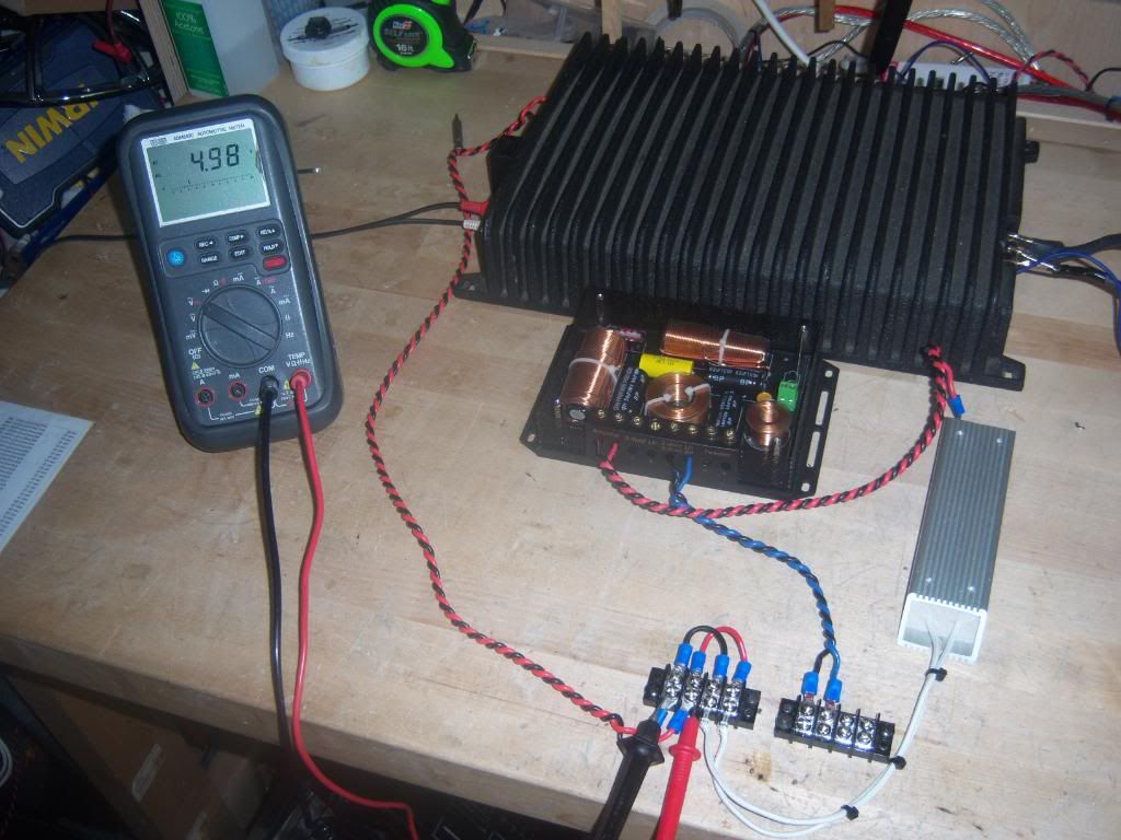
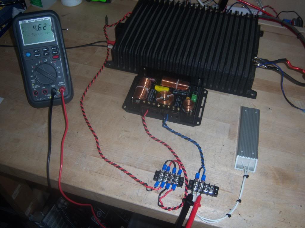
Now still at 5 volt AC output..... but the amp is now driving the resistor with the xover inline and the measurement is still taken @ the resistor

Image


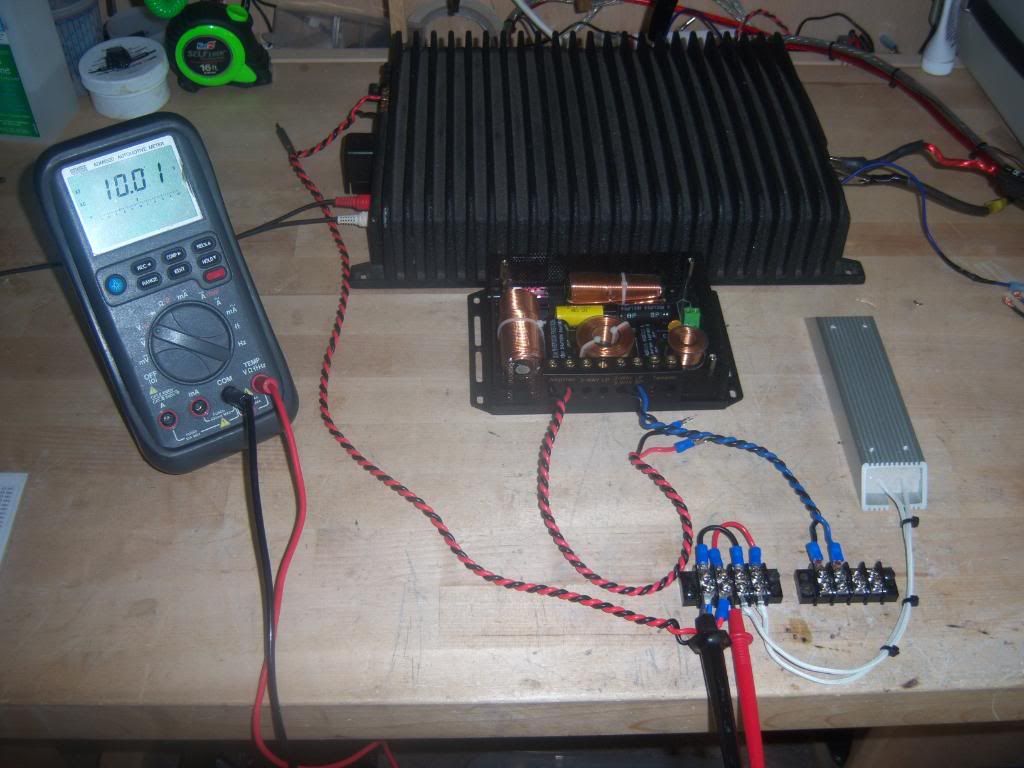
Next @ 10 volt AC.... the amp is driving the resistor directly

Image

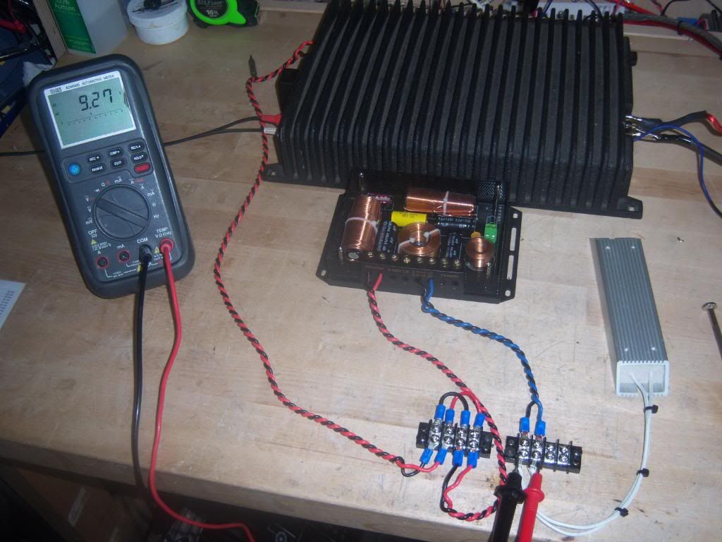
Now still at 10 volt AC output..... but the amp is now driving the resistor with the xover inline and the measurement is still taken @ the resistor

Image


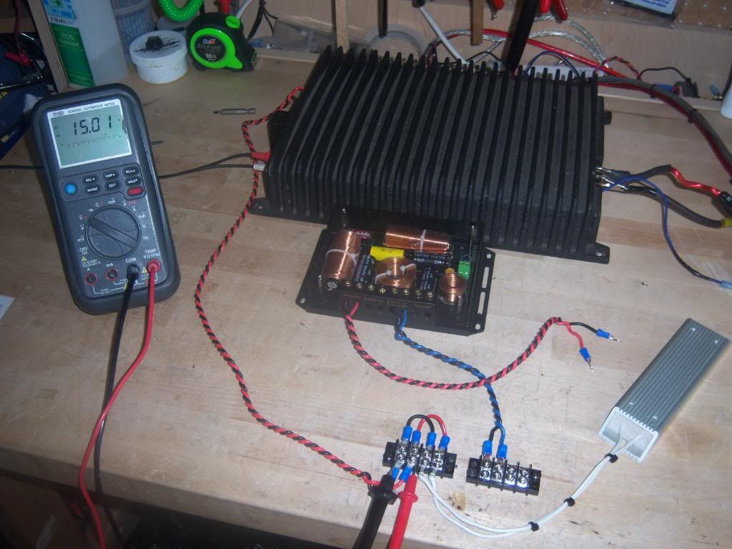
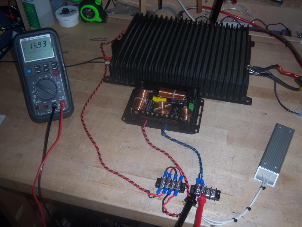
Next @ 15 volt AC.... the amp is driving the resistor directly

Image

Now still at 15 volt AC output..... but the amp is now driving the resistor with the xover inline and the measurement is still taken @ the resistor

Image


From these results, it's pretty easy to see that the xover is causing a voltage drop.

Here's a little math to go along with the findings:

First test: 4.98Vac with a 4 ohm load equates to 6.2 watts (Voltage squared/Resistance) and with the xover inline, we get a reading of 4.62Vac or 5.34 watts. This is a total voltage drop of .38Vac or .86 watts. A loss of .86 watts equates to approximately a 7.21% loss of power

2nd test: 10Vac @ 4ohm = 25w. Xover inline= 9.27Vac or 21.48w for a loss of 3.52w.....7.1% loss of power

3rd test: 15Vac @ 4ohm= 56.25w. Xover inline= 13.93Vac or 48.51w for a loss of 7.74w.....7.27% loss of power

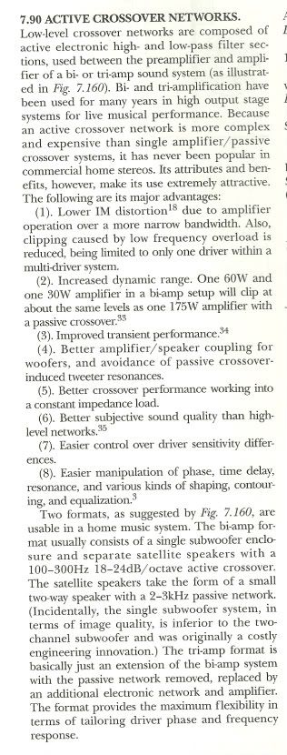
Now granted this is just for this particular xover, but like I said before, these findings are very similar to the "high-end" Ti elite crossover I had tested before. These results are also right in tune with what smgreeen had quoted from Vance Dickason that passive crossovers disipate approximately 5% of the power applied to them.

Also keep in mind that this is just a 2nd order (12db/octave) design. A 3rd or 4th order design will present even more of a voltage drop. :shock:
Another note: These findings were only with 100hz applied. As the frequency goes higher (for the "low" output) the voltage drops become even greater!!! :shock:

I understand that a 5,6,7% loss of power may not sound like much, and that's fine. Nevertheless, the point is these crossovers DO INDEED rob power, however large or small it may be.

If anyone would like to try this test on his own, I'ld be happy to help with any questions.
AKA "THE HATER"
User avatar
shawn k
Posts: 757
Joined: Thu Apr 01, 2010 2:33 pm
Location: Maine

Re: Has anyone had madisound custom build you crossovers?

Post by shawn k »

Here is a paragraph that I scanned from The Loud Speaker Design Cookbook by Vance Dickason. (sixth edition, page 152) Here he explains the benefits for an Active crossover.

*** If anyone wants to dispute Vance......... then they're a nutcase :? !!***

Image


Ok so please read benefit #2 again! :shock:

And read it again! :shock:

And how about one more time! :mrgreen:
AKA "THE HATER"
User avatar
Eric D
Short Bus Driver
Posts: 4259
Joined: Sat Dec 30, 2006 8:50 am

Re: Has anyone had madisound custom build you crossovers?

Post by Eric D »

Shawn,

Great test! I have no real complaints with your setup.

However, do you have any more crossovers you can try out? Just from your photo I see at least 9 components in that crossover.

A 12db crossover only needs 4 parts, a coil and cap for the mid and another coil and cap for the tweeter. Is it 12db on the mid and 24db on the tweeter? If so, that still should only be 6 parts in all (caps and coils).

I have a feeling there may be more going on with your crossover than you expect. If it is only a 12db type, you probably have a few notch filters in there as well, and one may even be near enough to the frequency you chose (100Hz) to affect your numbers.

Next, I am not so sure of findings as far as loss of power goes. To accurately measure power you need to measure the current as well, so I am more inclined to think that the passive crossover is "blocking" the power (some fraction of it), instead of "dissipating" it. But, I am not going to nit pick this point with you, as accurately measuring the power with a pair of meters is going to become a pain, and I don't want you to expect the same of me, so I give you a pass on this point.

One more item, do you have another load resistor? Since we don't have a schematic for your crossover and it is at this point just a "black box", you may want to consider putting something on the tweeter output as well. It is very rare but I have come across crossovers which were not stable with one driver missing. If this were the case, the tweeter section might be drawing a lot of current, which pulls down the amps feed overall. Again this is very rare, so I really doubt this is happening in your case.

But, all and all you have really shocked me. I never figured you would actually stand behind anything you say with an experiment such as this, so I owe you a lot more respect for taking the time to do this.

Now down to the basement I go to try and duplicate your results...
Got "schooled" by member shawn k on May 10th, 2011...
No longer really "in tune" with the audio industry, and probably have not been for some time.
Hands down the forum's most ignorant member...
Don't even know what Ohm's law is...
User avatar
Eric D
Short Bus Driver
Posts: 4259
Joined: Sat Dec 30, 2006 8:50 am

Re: Has anyone had madisound custom build you crossovers?

Post by Eric D »

As for the clip out of the Loudspeaker Cookbook, I guess I am a nutcase then.

I would really want to see the input signal which validates statement number 2 he makes. If one were to play a sine wave at 100Hz (like in your test) recorded at 0db, then the active low pass amp would indeed clip before the amp running the passive setup (assuming 60w, and 175w like he states).

Now, I don't listen to sine waves, nor does anyone else here (so I hope). But, music can be a lot of things. Playing something like country for instance will probably do exactly as he states, increase the dynamic range, and clip later with the active setup.

Now switch to rap, or even worse techno bass music. These types are music are so bass heavy, they don't leave much dynamic range for the high frequencies to ride on without clipping. With music like this, so much of the signal will be sent to the low pass amp, it will end up clipping much closer to the point it would if you just ran a sine wave into it.

So, yes I do agree with Vance, but not in every single case out there. I think he makes more of a "general guideline" statement here, not an absolute.
Got "schooled" by member shawn k on May 10th, 2011...
No longer really "in tune" with the audio industry, and probably have not been for some time.
Hands down the forum's most ignorant member...
Don't even know what Ohm's law is...
User avatar
shawn k
Posts: 757
Joined: Thu Apr 01, 2010 2:33 pm
Location: Maine

Re: Has anyone had madisound custom build you crossovers?

Post by shawn k »

Eric D wrote:Shawn,

Great test! I have no real complaints with your setup.

However, do you have any more crossovers you can try out? Just from your photo I see at least 9 components in that crossover.

A 12db crossover only needs 4 parts, a coil and cap for the mid and another coil and cap for the tweeter. Is it 12db on the mid and 24db on the tweeter? If so, that still should only be 6 parts in all (caps and coils).

I have a feeling there may be more going on with your crossover than you expect. If it is only a 12db type, you probably have a few notch filters in there as well, and one may even be near enough to the frequency you chose (100Hz) to affect your numbers..
Good eye, but this is an interesting crossover. This has the ability to do either 2way OR 3way. In 2way mode, it bypasses what would be essentially a bandpass output for the midbass driver.. therfore you can quickly eliminate 4 of the internal components. And yes, I checked and double checked that it was in 2way mode! So I assure you that there's not anymore going on in there that I'm not aware of... there are no notch filters present for this xover 8)
Eric D wrote:Next, I am not so sure of findings as far as loss of power goes. To accurately measure power you need to measure the current as well, so I am more inclined to think that the passive crossover is "blocking" the power (some fraction of it), instead of "dissipating" it. But, I am not going to nit pick this point with you, as accurately measuring the power with a pair of meters is going to become a pain, and I don't want you to expect the same of me, so I give you a pass on this point...
Ahhhh what? Man, I was so afraid of this. Apparently you cannot even comprehend what I did here. And to say "To accurately measure power you need to measure the current as well" is complete bullshit man!!! Evidently Ohm's Law means nothing to you :idiot: Power can be calculated "SIMPLY" where P= Voltage squared divided by resistance... This is fundamentals man.. You should know this stuff if you're even to attempt at debating this subject! :naughty: :roll:
Eric D wrote:One more item, do you have another load resistor? Since we don't have a schematic for your crossover and it is at this point just a "black box", you may want to consider putting something on the tweeter output as well. It is very rare but I have come across crossovers which were not stable with one driver missing. If this were the case, the tweeter section might be drawing a lot of current, which pulls down the amps feed overall. Again this is very rare, so I really doubt this is happening in your case.
Nope, no smoke and mirrors here man... nice try though :roll:
AKA "THE HATER"
User avatar
shawn k
Posts: 757
Joined: Thu Apr 01, 2010 2:33 pm
Location: Maine

Re: Has anyone had madisound custom build you crossovers?

Post by shawn k »

Eric D wrote:As for the clip out of the Loudspeaker Cookbook, I guess I am a nutcase then.

I would really want to see the input signal which validates statement number 2 he makes. If one were to play a sine wave at 100Hz (like in your test) recorded at 0db, then the active low pass amp would indeed clip before the amp running the passive setup (assuming 60w, and 175w like he states).

Now, I don't listen to sine waves, nor does anyone else here (so I hope). But, music can be a lot of things. Playing something like country for instance will probably do exactly as he states, increase the dynamic range, and clip later with the active setup.

Now switch to rap, or even worse techno bass music. These types are music are so bass heavy, they don't leave much dynamic range for the high frequencies to ride on without clipping. With music like this, so much of the signal will be sent to the low pass amp, it will end up clipping much closer to the point it would if you just ran a sine wave into it.

So, yes I do agree with Vance, but not in every single case out there. I think he makes more of a "general guideline" statement here, not an absolute.


Oh brother :roll:

Unbelievable... just unbelievable :(
AKA "THE HATER"
Post Reply