My M-series project

Need help with your car stereo system? Have a technical question? Post here.
Post Reply
wheelieking71
Posts: 199
Joined: Wed Apr 29, 2009 6:42 pm

My M-series project

Post by wheelieking71 »

Wasn't exactly sure where to put this, since its technically not going to be car-audio. But, it seems like as good a place as any.

A little preface about the project: I want a rockin' system in my shop! LOL! Since I am somewhat of a 12v amp junkie, and I have a fairly robust power-supply (ASTRON RS70m), and I want to use active crossovers, it only makes sense for me to use 12v amps. Plus building this rig will be a really fun project.

A while back I picked up a few case-less M25's. I am a machinist, and I also like to machine parts for amps. So, I scooped up those M25's knowing I could do something with them. I was originally going to build a staggered 4-ch amp with them. Two of the amps pridged, and one stereo. In a tower arrangement. It would have fit well in the center console of my truck. Here was the mock-up:
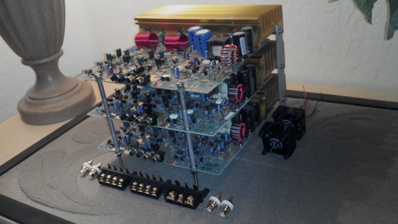
Image

But I ended up going a different direction in the truck, and kinda forgot about these guys. Now that I have had my shop open for about a year, and spend a ridiculous amount of time there, I would really enjoy a nice system. While I was shopping for 120v amps, and trying to figure out how I was going to accomplish an active crossover (on the cheap!) I remembered these guys, and my ASTRON! So I drug them back out.

That's when I got to thinking, "hmmm, I could really use more power". So I started hunting for a pair of M50's for subwoofer duty. Took a few weeks, But i managed to round a couple up (one is still en-route from overseas). And finally, I picked up an ALPINE CDA-9887 to use for a source. I figured a head-unit would be a good solution to a source, and processor all in one. And I am very familiar with the 9887. When one popped up super cheap, I snagged that too.

So, The plan for wicked shop tunes is set. ASTRON for 12v power, 9887 as a source, Phoenix Gold M-series for power! The only thing still in the air is speakers. I have three M25's, and two M50's. I am sure that I will run both M50's each bridged on a nice 12" sub in a ported enclosure. Then for the top end, I am undecided. I will either bridge two M25's, each on a midwoofer, and the third M25 will power tweeters. OR! I will simply bridge two M25's, each powering a nice full-range driver. I am really leaning towards the full-ranges for a few reasons. One, efficiency. There are some nice efficient drivers that will get plenty loud off 100watts, and still sound fantastic. And I really could care less about imaging. This whole rig will be parked on some pallet-racking in the back of the shop. And, I will already be pushing the limits of my available 70amps with just the M50's, let alone three added M25's. So, I will most likely just run the two M25's and full-range drivers.

I will fabricate a chassis for all this. It will be cool. But, I am getting ahead of myself a little bit there.

First things first. These OLD amps need some attention! So tonight I pulled the heat-sinks off one M25, and one M50. The sink needed to come off the M25 because I wanted to swap the sun faded sink on one of my boards out for another nice one that matches the rest I happen to have. And The sink needs to come off the M50 because I want to perform Eric's resistor mod. To get them up and away from the board. The board on this amp happens to be baked pretty good. It has not failed. But, definitely is a perfect candidate for the mod.

It is at this point that I would like to ask for some help if I could! First: I can't find a schematic for the M50, and I dont know how to read resistors. Can anybody tell me what the value of these guys is?

Image

Can anybody confirm the values for the 4 dudes dead center of the above pic?

And then, while popping the transistors free from the sil-pads:

Image

WTH? I have never seen this happen before! LOL. Do I need to replace these as a set? And, its obviously an IRFZ44. But, which variation should I order? I have found several!

And finally:

Image

I am guessing I don't need to worry about this one? Is this just cosmetic? Or should It be replaced?

I am comprising a big ole' parts list, and any help on determining just what I need, would be greatly appreciated!
ttocs
the Floor Sweeping Hack with Golden Ears
Posts: 14797
Joined: Fri Dec 19, 2008 9:53 pm

Re: My M-series project

Post by ttocs »

brown black black on resistors is a 10 ohm resistor.
what else can I say I am a grumpy asshole most of the time.
zeropoint0.5
Posts: 593
Joined: Fri May 13, 2011 12:03 am

Re: My M-series project

Post by zeropoint0.5 »

ttocs wrote:brown black black on resistors is a 10 ohm resistor.
x 2....they are indeed 10 ohm resistors....

i had this problem solved once on a M50,and, inspired by a former topic of Eric D. i replaced those

4 resistors even with a 3w model and away from the board so they would have good contact with the

heatsink, i even putted some cooling paste on it............ it seems to be a typical problem with these amps.....


nice project you're doing by the way.....try to finish it with a creation in plexi and it will look awesome !!!!!


i don't think you have to replace that output transistor for that reason..............seen before........


replace the 4 irfz44 with a irfZ48 model and you'll be fine.....you can use same value of gate resistors here.....

but check if they are still fine................
User avatar
Eric D
Short Bus Driver
Posts: 4259
Joined: Sat Dec 30, 2006 8:50 am

Re: My M-series project

Post by Eric D »

This link may help you in the future...

http://www.sorion-group.com/Resistor/resistor.htm

I personally would replace any chipped transistor, even if it did work. Exposing the inner core of the transistors just does not seem like it would be reliable long term. Electronic parts do corrode, and with an exposed core, I would not want to see what happens when it starts to corrode.
Got "schooled" by member shawn k on May 10th, 2011...
No longer really "in tune" with the audio industry, and probably have not been for some time.
Hands down the forum's most ignorant member...
Don't even know what Ohm's law is...
wheelieking71
Posts: 199
Joined: Wed Apr 29, 2009 6:42 pm

Re: My M-series project

Post by wheelieking71 »

Thanks guys! That all helps. Eric, thanks for the link, very cool!

So far the only source i can find for the chipped Toshiba 2SC3281 transistor is to buy used ones off ebay. Is that a safe buy?

And, will this work for the IRFZ: http://www.mouser.com/ProductDetail/Int ... utm1oJQ%3d
trickyricky
Posts: 1653
Joined: Sun May 06, 2012 8:01 am

Re: My M-series project

Post by trickyricky »

I would replace those resistors with to-220 package. The to-220 can handle up to 35watts compared to a 3watts and they can easily be mounted to the heat sink (look below and you'll see you have space for them, a little modification and wallah).

I couldn't help but notice that the M50 has the original filter caps, you have to replace those caps as well. Any cap labeled "HF" needs to be replaced ASAP.
wheelieking71
Posts: 199
Joined: Wed Apr 29, 2009 6:42 pm

Re: My M-series project

Post by wheelieking71 »

Yea, I just stripped the input, and rail caps out of that M50 (sorry Eric, I know you hate when the rail caps come out LOL).
I only lost 3 solder pads, and 0 VIAs!

Not bad for a complete rookie :oops:
zeropoint0.5
Posts: 593
Joined: Fri May 13, 2011 12:03 am

Re: My M-series project

Post by zeropoint0.5 »

wheelieking71 wrote:Thanks guys! That all helps. Eric, thanks for the link, very cool!

So far the only source i can find for the chipped Toshiba 2SC3281 transistor is to buy used ones off ebay. Is that a safe buy?

And, will this work for the IRFZ: http://www.mouser.com/ProductDetail/Int ... utm1oJQ%3d
http://be.mouser.com/ProductDetail/Inte ... bvXV2IM%3d

no it's this one........
wheelieking71
Posts: 199
Joined: Wed Apr 29, 2009 6:42 pm

Re: My M-series project

Post by wheelieking71 »

zeropoint0.5 wrote:
wheelieking71 wrote:Thanks guys! That all helps. Eric, thanks for the link, very cool!

So far the only source i can find for the chipped Toshiba 2SC3281 transistor is to buy used ones off ebay. Is that a safe buy?

And, will this work for the IRFZ: http://www.mouser.com/ProductDetail/Int ... utm1oJQ%3d
http://be.mouser.com/ProductDetail/Inte ... bvXV2IM%3d

no it's this one........
GOT IT! Thank you Sir!
wheelieking71
Posts: 199
Joined: Wed Apr 29, 2009 6:42 pm

Re: My M-series project

Post by wheelieking71 »

Caps stripped from one M50:

Image

And the results of just yanking the input-caps from the M25 board behind it. Much easier that way!!!!!!! Must have had some cold solder joints as 3 out of 4 leads came right out of the board with no damage to the board what-so-ever.
Top side:

Image

leads popped right out of the board. Bottom side:

Image
wheelieking71
Posts: 199
Joined: Wed Apr 29, 2009 6:42 pm

Re: My M-series project

Post by wheelieking71 »

And the M25 rail-caps out with no board casualties!

Image

Image

I know they probably didn't need to come out. But, I am a glutton for punishment. And I have a decent amount of practice fixing pads, and VIAs from learning how to do this on some old ADCOM amps. It seems if you even look at those boards crooked, the solder pads jump right off! LOL, these M-boards are far more robust than the ADCOMs I am used to.
wheelieking71
Posts: 199
Joined: Wed Apr 29, 2009 6:42 pm

Re: My M-series project

Post by wheelieking71 »

M50 board didn't fair so well at the hot resistors :( . There will be some hard-wiring going on when it goes back together.

top side looks "okay":

Image

Everything is starting to lift, and the heat the board has endured is obvious.
The bottom is not so good:

Image

I lost one solder-pad, and the center trace that bridges two resistor legs lifted and broke off.
Getting the resistors themselves out, was easy. The problems started when trying to clear the solder out of the through holes. Since everything was lifting, I think the connections to the VIAs was weak and not transferring heat. The solder-sucker was not doing a dang thing LOL. Oh-well. I will doctor it all back up. A little hard-wiring never hurt nobody LOL.
zeropoint0.5
Posts: 593
Joined: Fri May 13, 2011 12:03 am

Re: My M-series project

Post by zeropoint0.5 »

on the M50 board, while you're busy, don't forget to replace those 2 330 ohm resistors with a 5w model and half an inch away from the board...

you find one of them just in the middle of both railcaps, the second one below the right railcap surrounded by some little caps............


don't forget to clean up the flux now after desoldering !!!!!!!!!!!
wheelieking71
Posts: 199
Joined: Wed Apr 29, 2009 6:42 pm

Re: My M-series project

Post by wheelieking71 »

zeropoint0.5 wrote:on the M50 board, while you're busy, don't forget to replace those 2 330 ohm resistors with a 5w model and half an inch away from the board...

you find one of them just in the middle of both railcaps, the second one below the right railcap surrounded by some little caps............


don't forget to clean up the flux now after desoldering !!!!!!!!!!!
Thanks for the tip zeropoint! I was not aware those two were an issue. Will do!

I just got on ebay, and bought a Panavise to help facilitate working on these guys. I have five of them to do. It would be so much easier if the board was stationary!
wheelieking71
Posts: 199
Joined: Wed Apr 29, 2009 6:42 pm

Re: My M-series project

Post by wheelieking71 »

These are the full-range drivers I am thinking of running: http://www.madisoundspeakerstore.com/ap ... ull-range/

They should be capable of filling a 1500sq-ft shop with sound.

Or maybe I will splurge, and pick up a pair of the TangBands I have been drooling over for a couple years now: http://www.parts-express.com/tang-band- ... r--264-894

Have to see how much I spend between then and now. I have a budget set, gonna try not to go over! LOL, we all know how that goes! :lol:
LowandLoud
Posts: 601
Joined: Sat Sep 08, 2012 6:52 am
Location: Cambridge Ont., Canada

Re: My M-series project

Post by LowandLoud »

Cool project man. I will be following this one for sure!

LL
Always looking for:

Install accessories
LE amps
Processing
Unique pieces
wheelieking71
Posts: 199
Joined: Wed Apr 29, 2009 6:42 pm

Re: My M-series project

Post by wheelieking71 »

So, I had time to strip the second M25 tonight. Got the rail caps out of this one, also with no damage:

Image

Not sure if the residue was from leaking electrolyte, or residue left from the factory solder job?

I actually have a much easier time getting the snap-ins out, and Vias cleared, than the through-hole stuff.

You guys that are good at this stuff, whats the trick for clearing the Vias? I am having a hell of a time getting them clear, with some! Some suck right out. Others absolutely will not clear.

A good buddy of mine taught me: flux, flow fresh solder, wick clean, flow solder again, solder sucker. It works perfect 3-4 out of 5 times. The smaller the Via, the tougher time I have. Getting a little frustrated feeling like I am doing more harm than good.
User avatar
KUBE
Posts: 26
Joined: Thu Jan 09, 2014 4:14 am
Location: UK Surrey
Contact:

Re: My M-series project

Post by KUBE »

I have just taken an M50 Revision A apart. My board is mint. One cap had a very tiny droplet of leaking, but overall it was one of the cleanest set of caps I have seen.

Also I note my resistors are different to the brown ones pictured above. Mine are smaller and blue. They all look fresh with no signs of browning or heat soak around them. I can only assume they swapped parts in the later revisions.

Okay a question. My M50 only had three caps, but space for four. I now have room to instal four as the new caps are lower in height. Shall I add the fourth or leave it out?

Thanks
WANTED - MINT M100 or M50
trickyricky
Posts: 1653
Joined: Sun May 06, 2012 8:01 am

Re: My M-series project

Post by trickyricky »

Its totally up to you (the owner), I personally would just stick two or three if the capacitance value is high enough. It should be as the new capacitors have more capacitance in a smaller package. Panasonic FC & FR is what I use, but many also like the HE from nichicon.

The original where 2200uf or 2900uf 16v, you can replace them with two 3900uf 25v (or higher) and be safe or use four of them as long as the closest one to the front panel is not tall enough to hit with the top cover when putting it back together.
Post Reply