repair zx350 w/ pics

Need help with your car stereo system? Have a technical question? Post here.
Post Reply
dkitt10
Posts: 38
Joined: Sun Aug 05, 2007 3:09 pm

repair zx350 w/ pics

Post by dkitt10 »

got a free zx350 v2 would like to fix it up....i don't know much about electronics though I can solder so I was hoping to just try this out see if I could get it to work

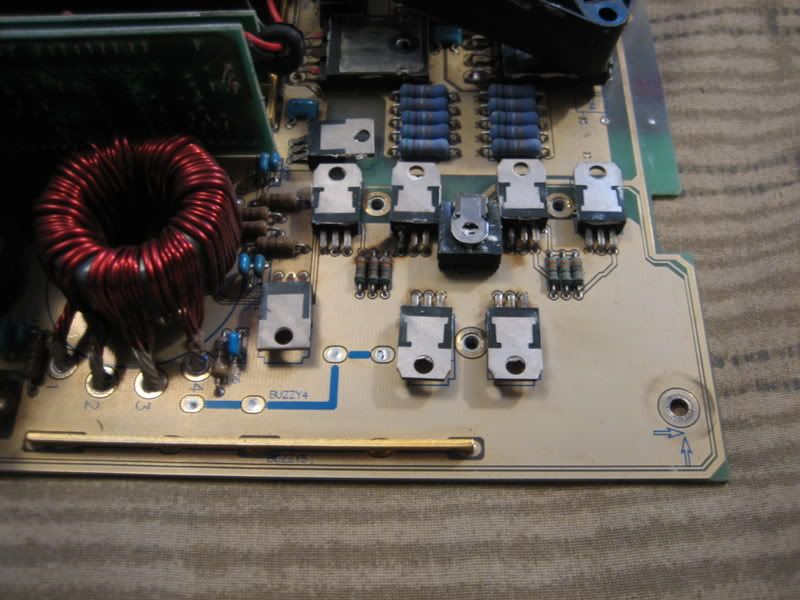
as for physical damage these are the only two area's on the board...

Image

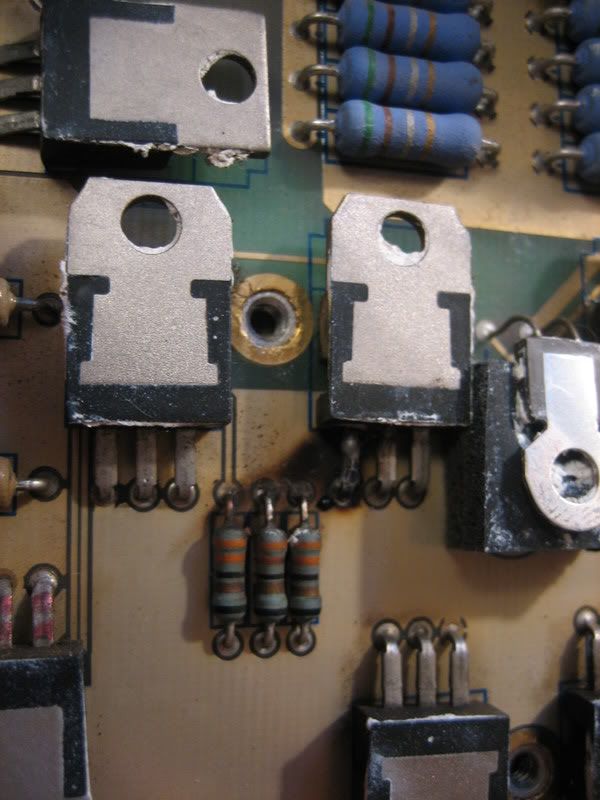
So problem is the 2nd and 3rd thinger in the row of 4 (what are those thingers called?)

close up of one on the left....

Image

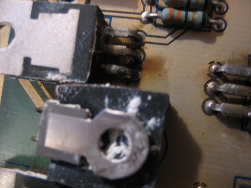
close up of one on the right....

Image

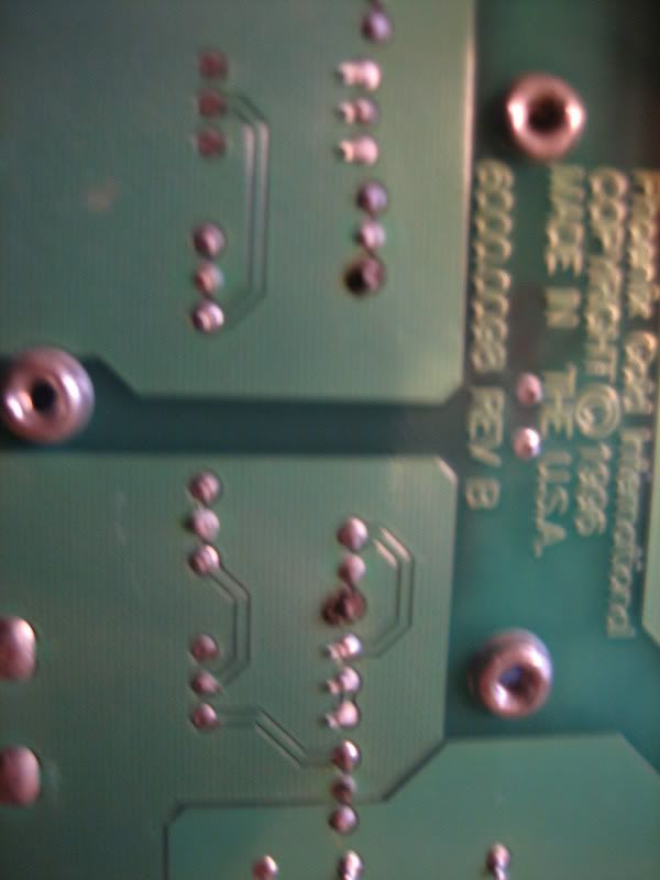
and well the one on the left I thought maybe those smaller set of 3 things woulda been damaged but i looked on the back and the solder points suggest only the bigger thingers were damaged (just the left leg blew out?)

Image


im sure I sound retarded but hey maybe you guys can teach me a thing or 2!!
1moreamp
NOT justonemoreamp
Posts: 2504
Joined: Sun Dec 10, 2006 8:53 pm
Location: No where special

Post by 1moreamp »

Ho Ho Ho You need some new Mosfets, and the little green resistors < orange, orange, black, brown > < 33 ohm FUSE type resistors.
The Fuse resistors blow when the Fets short as a protection to keep the amp from burning the board up. < Fire protection device please pay attention to the correct replacement device here>

You also might have damage on the upright board that contains the PWM power supply controller chip located to the right a bit.

Power supplies USUALLY don't blow out for no reason. I would ohm out the outputs and rectifiers as a matter of good practice. Only on rare occasions will the power supply blow on its own without other causes.

The MosFets are 70N06 types I have used several quality replacements depending on my objective with the repair.
My normal replacement would be the exact part or equivalent like a RFP70n06.
Upgrades would be a IRF-1010, and IRF-3205 as a super Max replacement.

Ho Ho Ho!!! Merry Christmas !......C
dkitt10
Posts: 38
Joined: Sun Aug 05, 2007 3:09 pm

Post by dkitt10 »

k well i need 2 RFP70n06


and for the 33ohm fuse type resistors...i looked on the net...they come in different wattages????
1moreamp
NOT justonemoreamp
Posts: 2504
Joined: Sun Dec 10, 2006 8:53 pm
Location: No where special

Post by 1moreamp »

Ho Ho Ho... replace all the fets, and the fuse resistors are 1/4 watt size... Did you ohm out the outputs ?

I hope you have a current limited power supply to retest this with. Its the only safe way I know of test firing a repaired amp. Even a cheap one like Astron makes is fine as long as you can turn down the max current to like 4 or 5 amps max, and can see what its drawing when you fire it up the first time.
If it does not draw proper idle current your still not out of the woods yet, but at least your not smoking the work you have completed by limiting the current to a safe level.....C :)
dkitt10
Posts: 38
Joined: Sun Aug 05, 2007 3:09 pm

Post by dkitt10 »

how do i ohm out the outputs??

oh and u mean like a power supply..plug it into the wall and gives you your dc voltage like they use for demo'in amps in stores and stuff??

cause i got one of those...
1moreamp
NOT justonemoreamp
Posts: 2504
Joined: Sun Dec 10, 2006 8:53 pm
Location: No where special

Post by 1moreamp »

dkitt10 wrote:how do i ohm out the outputs??

oh and u mean like a power supply..plug it into the wall and gives you your dc voltage like they use for demo'in amps in stores and stuff??

cause i got one of those...

I have attached a picture of a economical adjustable current limitable power supply. You will notice the two adjustment knobs one is for voltage the other is output current limit.
At my shop all the techs have one of these. Its adjustable so you can limit power to the device under test and therefore protect all your hard work IF you missed something....This sort of work demands the correct tools, this is a example of many possible brands that will perform the work without causing damage in case you missed anything.....Ho Ho Ho...
Attachments
Variable power supply with adjustable current limits
e0e1_2.JPG (5.81 KiB) Viewed 6116 times
1moreamp
NOT justonemoreamp
Posts: 2504
Joined: Sun Dec 10, 2006 8:53 pm
Location: No where special

Post by 1moreamp »

Ohming out the output transistors requires a DMM. I prefer a auto range model but tastes vary. I use the ohms range NOT the Diode continuity check which is limit to 100 ohms or less.
Transistors read in the hundreds of ohms and up range, and only read low ohms in certain configuration like found in Hifonics and PPI amps.

You will be looking for 10 ohm or less reading across any two of the output transistor legs.


I am not trying to be mean or anything, but it is apparent that you are of a novice level at this sort of thing. I am not, I have been doing this for a very long time so I can talk about it in my sleep. Yes I am old, but try not to hold that against me :lol: :lol: :lol:
If you are new to this sort of thing like I think, there is a better web-site for you to get trained on. I will try to attach the sites below:

Basic Car Audio Amplifier Repair http://www.bcae1.com/repairbasicsforbca ... basics.htm
Basic Car Audio Electronics http://www.bcae1.com/


I know the guy who wrote this web-site and hes a pretty sharp person, and he has put a lot of energy in these sites to help teach and train you on the things you need to know to start out in what you are attempting to do.

I highly recommend that you take some time on these sites before you proceed further. I make this point to aid you in a fashion that will accommodate your own independent learning speed.

Otherwise the things I will be posting will start to sound more and more foreign to you, and it will detract from the true speed of how fast this amp can be repaired < I.E. less than a hour typically>
In fact I usually spend more time on the simple things like assembly and testing then it requires to actually repair a amp of this size.


Please consider my advice as sound and in your best interests, as I wish only to help you. The simple tests you need to perform are outlined on these sites, so you can read and practice as you progress. I am sure it will be smoother for you then waiting for my attendance here on this site, especially at Christmas time......C :)


Ho Ho Ho Merry Christmas !!! :D
dkitt10
Posts: 38
Joined: Sun Aug 05, 2007 3:09 pm

Post by dkitt10 »

thank you so much...i understand completely what your getting at and yea this is defintly a learning project

I'll grab one of those doo hickies when i go back home for christmas


my dad has all that stuff...he fixed tv's and amps and all that stuff for like 30 some years

he's actully the one who got me into phoenix...he was a dealer for years and has repaired amps for just as many

I kinda wanted to do this with out his help thats why im here...but hey is doesnt do it anymore and has all that kinda of equipment so ill be sure to take it back home with me...any other equipment i should grab that is used for repairing and testing amps??

thanks again for all your help!!
1moreamp
NOT justonemoreamp
Posts: 2504
Joined: Sun Dec 10, 2006 8:53 pm
Location: No where special

Post by 1moreamp »

At your level a good DMM and a Variable power supply are the most you should need for now. The other tools get even more complex in their application and execution.

So lets start with basics and then move up later as you get more trained at the technology....Ho Ho Ho Merry Christmas ! :) :) :)


PS I consider these two tools a must if your really trying to get the job done safely and correctly. I watch the idle current draw of a amp in paticular and the DC offset at the output as a Go-No-go test of As Is quality of the amp and possible needs it may have. The rest of the tests are complex requiring Signal generators and distortion analyzers, and scopes etc.... So you see there are the simple tests that tell all, and the complex ones that yield the raw data that must be engineered through to get solutions....C
Post Reply