Hey this is great that I found this forum!
I have a M50 and M44 which I bought in 1994. They have been sitting in my attic for about 10 years now and I just bought a 05 325i and am in desperate need to improve the sound...
My 325i speaker setup is as follows:
Front doors: 1" tweeter, 2.5" midrange, 6.5" midbass
Rear Deck: 6.5" midbass, 2.5" midrange
So, I did some reading about 2volt gains or something about new cars and maybe there can be an issue..
Any thoughts on how I can use them? Any PM I should do to the amps before I use them since they're pretty old? I read one post here where an M50 caught fire. Do I need to replace the caps? Is there some bench testing I can do to make sure they are up to spec?
Thanks!!
M50 and M44 - advice
Welcome to the Phorum! you've definitely come to the right place. There's a couple of guys who will be able to help you. If you have the ability to open them up and take pictures of the insides, I am sure some of the guys on here can help you a bit more. And you may just want to replace the caps if they've been stored for that long. And since it looks like they have been in use for close to 3 years?
Morning, and welcome to the phorum!
You should look into getting new caps. Caps die of old age weather they are being used or not < just my 2 cents worth about caps>.
By my experience replacement of the caps is akin to a overhaul before you hit the road again with your amps. The amps will sound better, and you will avoid the major issue of using 15 year old equipment.
Doc Fosgate has a few posts about this procedure both here and elsewhere. His posts have nice pics, and will give you a idea of how much work is involved, and what you will avoid by performing this routine maintenance.
Heres a pic tutorial by Doc about the damage bad caps can bring and his repairs that he is known for, please see the link below:
http://phoenixphorum.com/ms2250-repair- ... light=caps
Both he and I do this sort of thing for folks here from time to time. He might be available to do yours also.
The other test you can do is posted in the How-to section is the DC offset test. In this test you hook power to the amp and no rca's, and no speakers, and read the DC output voltage of each channel.
This is a simple but reliable test that can tell anyone if there are sonic issues with your amp. Heres the link below:
http://phoenixphorum.com/amplifier-dist ... t3428.html
well that should get you started with some light reading. You can search the site using key words to find and relevant posts you might be looking for.
Welcome to our home, we hope you like what you find here....C
Thanks guys.. Good info indeed.
So it looks like I should be changing my caps and do a dc offset voltage check before putting these amps into service...
Naturally, my next questions
1. What size caps and where do I get them? Approximate cost?
2. Any cap replacement writeups to reference?
3. If my DC offset is not within spec how or what fixes it? I read the post and the warnings about adjusting the wrong pots but I'm sure I can handle it provided a bit of education on the procedure.
Thanks again.. Great place here!
BTW - anyone know where I can find the published specs (or real world specs) for these amps?
denisl wrote:
1. What size caps and where do I get them? Approximate cost?
2. Any cap replacement writeups to reference?
3. If my DC offset is not within spec how or what fixes it? I read the post and the warnings about adjusting the wrong pots but I'm sure I can handle it provided a bit of education on the procedure.
Thanks again.. Great place here!
BTW - anyone know where I can find the published specs (or real world specs) for these amps?
Answer to 1 and 2 :
http://phoenixphorum.com/ms2125-leaking ... nt+fosgate
Answer to #3 is to contact either myself or Doc Fosgate directly as the work is techy level and takes a bit of back and forth to cover, as you will be actually repairing your amp internally...C
Which tech specs are you looking for ? the M-44 and 50 ? If so I can find and send those to you, PM me a e-mail address to mail them to, and any other spec sheets you might want or need. I will dig them up from the archive.....C
C - thank you again. The replacement procedure link and information you provided is excellent. I'm going to get my amps today (at my parents house) and open the lids and take some pictures... I'll have to read the posts in the link you sent me about 100 times before I attempt the replacement.
This sounds like a fun job and a good excuse to buy some tools
My email is xxxxxxxxx
Is there a spec / data sheet for the amps published by PG?
This sounds like a fun job and a good excuse to buy some tools
My email is xxxxxxxxx
Is there a spec / data sheet for the amps published by PG?
Last edited by denisl on Mon Dec 31, 2007 10:37 pm, edited 1 time in total.
denisl wrote:Hey C - I just read through those posts and am not clear on what dimension the caps need to be.
Do you have a part number or specs so I get the right ones?
How many do I need for my M44 and M50?
Thanks!!
Part numbers might just add more troubles as you would be corralled into buying from one source, and paying their price.
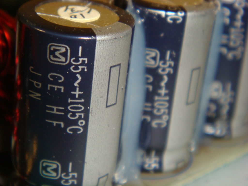
I am posting a pic of a last run MS-1000 from PG ( Thanks Nico) and there selected caps, which are the exact same that I stocked myself. They are Nichicon 105 degree C rated low to ultra low ESR rated.
As for value, PG used 2200 UFD at 16 volts DC. I use 6800UFD at 16 volts DC. I have seen 25 and 35 volt caps used here by other makers.
The big deal is height.... These things can't exceed a certain physical height. and that height is 28 to 35 MM, with 35 MM being the MAX height possible inside the amp package. There will be 4 in the M-44, and 3 in the M-50 < and the M-50 will need 28 MM max height due to location.>
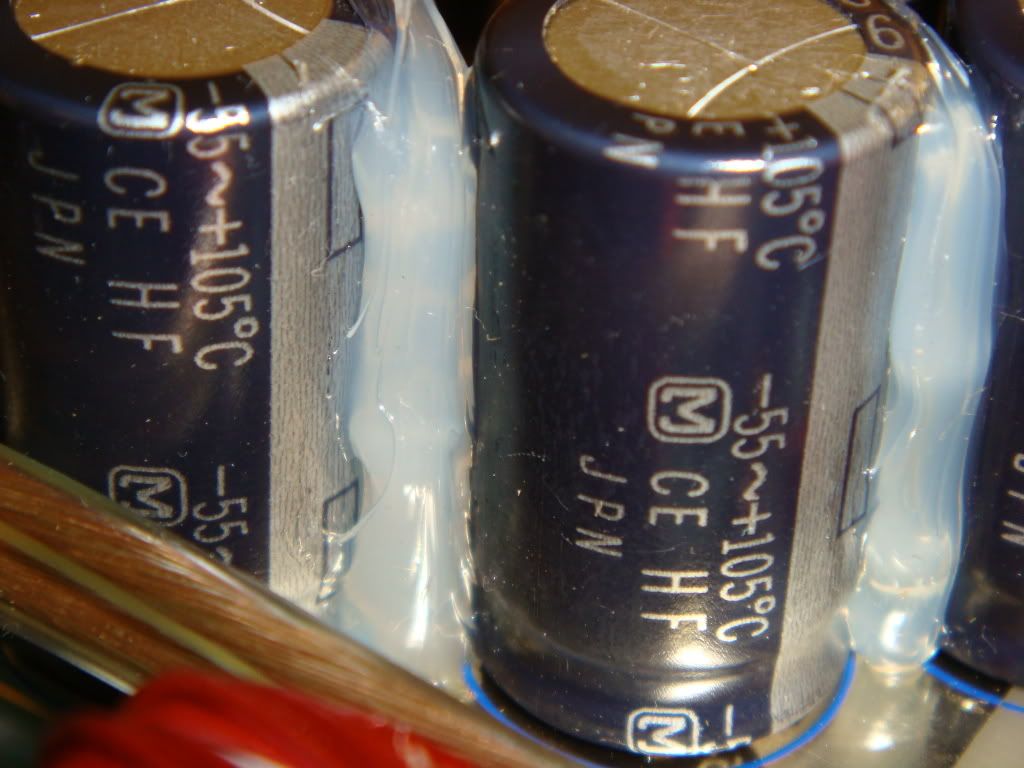
There are other caps that MAY need to be replaced. The little ones are fairly cheap to come buy. You will see these as they will have the plastic labels that have shrunk from heat. Just look for plastic wrappers that don't cover the can evenly anymore.
Then there are the big black, or Blue caps located towards the middle of the amp. These are the largest of all the caps in the amp, and the cost the most.
Upwards of $12.00 each from PG. Yes PG can sell you caps also, but with a little independent searching you can save money buying from the many sources available on the net and worldwide.
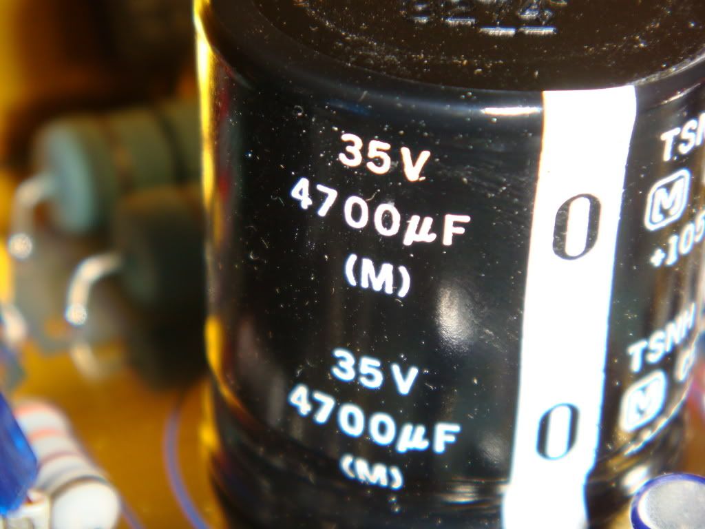
These bigger caps are the internal rail caps. they have a 35MM MAX height and are also rated at 105 degree C rating. The M-50 has a set of 2 each 4700UFD at 35 Volts Dc rating and are 35Mm high by 25 MM wide but you can replace them with up to 35MM wide caps in the M-50.
The M-44 has 15,000 UFD rated caps at 35 volts DC rating, and are 35MM X 35MM size and 105 degree C of course. 2 Each in each amp...
I swear by Nichicon Caps. I have never had any issues using them EVER. and that is many years of history speaking not a guess. Are there better out there, maybe. But Nichicon has a name and quality history unmatched in the business, so I go with what I know works and leave it at that.....
Well these enough info to make you pull you hair out, but if you open you amps up and take a pic or two and measure them with a ruler and then write down all the numbers on them, you will have everything I have posted above for you.
Caps can be bought from PG, Digi-Key, Mouser, and many others. I am posting a part finder link below, just click on it and type in the description or value of the item and the link will search the net for you to get these parts found and their prices...
http://www.findchips.com/avail
Remember to buy the best grade of cap possible and affordable. These are the highest rated temp wise and usually have the same UFD value or higher in the same size package, so they will fit properly inside the amps.
Remember smaller size is OK as long as you don't skimp on grade and value in "Micro-Farads".......C
- Attachments
-
- Nichicon caps in brown 2200ufd @ 16 VDC < stock value> Thanks to Nico for the pic.
- MS-1000 current caps.JPG (472.39 KiB) Viewed 20362 times
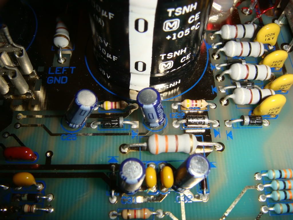
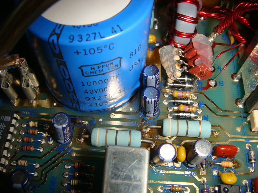
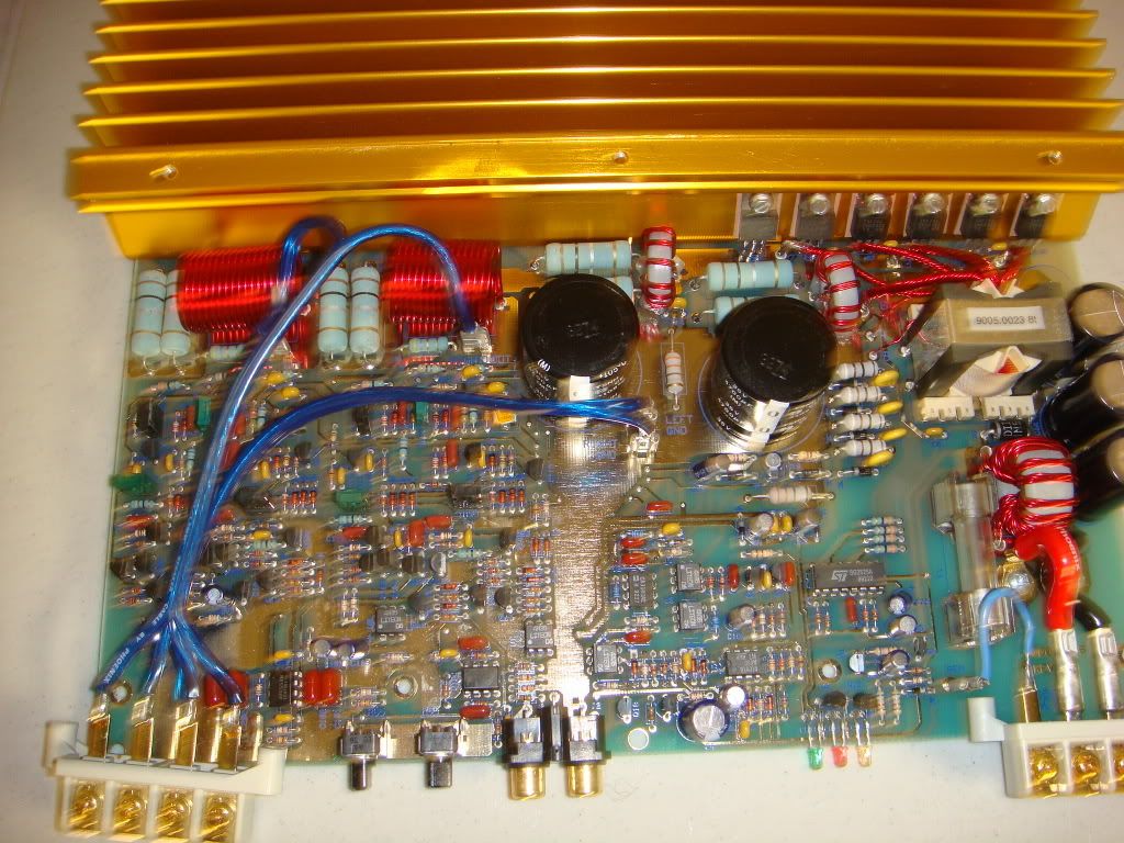
I have my amps apart and see what your talking about. Here are some pictures of the insides. I'm finding it a bit complex locating the capacitor type I guess because the terms are somewhat unfamiliar to me. For example, ESR (resistance), Lead spacing, mounting type (snap, etc)..
So this is what I think I need....
M44:
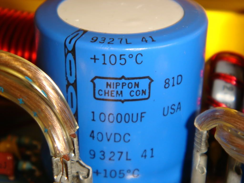
Big caps: 10,000uf 40VDC 105deg
Small caps: <Not sure can't see it on the cap see pic>
M50:
Big caps: 4,700uf 35VDC 105deg
Small caps: not sure
Here's the pics:
M44 :
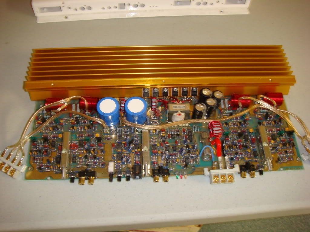
M50 :
So it looks like PG went to 15000uf caps after my amp was made since I have 10000uf caps in my M44. And the small caps are identical in both amps so in total I need 3 types of caps.
So this is what I think I need....
M44:
Big caps: 10,000uf 40VDC 105deg
Small caps: <Not sure can't see it on the cap see pic>
M50:
Big caps: 4,700uf 35VDC 105deg
Small caps: not sure
Here's the pics:
M44 :
M50 :
So it looks like PG went to 15000uf caps after my amp was made since I have 10000uf caps in my M44. And the small caps are identical in both amps so in total I need 3 types of caps.
There are a few private ideas of mine that I use to install these. I posted them earlier but have forgotten which post, so I will repeat the basic info again here.
Now when replacing these caps you are staving off a major failure of this series of amp, BUT,,, New caps will do the same thing after 10 to 15 years of service.
New caps are just a repair, not a true fix of this problem. There are a few things you can do to help prevent board damage later on just in case you have the bad luck of springing a leak in the new caps your installing.
My improved installation method requires that you buy a tube of RTV sealent and clip the tip at a small angle so you can place a bead of RTV under the cap between its wires.
There is a small channel located in the middle of the soft rubber foot of these smaller caps. I run a small bead of RTV < just enough to seal the cap to the board and ooze out just a bit after install>
Now this does two things, 1: its helps to connect the cap to the circuit board and reduce any induced vibration related issues, and 2: it provides a block to any leakage from staying under the cap and causing the board damage that the chemicals do when they do leak.
You see I have looked at this problem, and its more than just a issue of buying and installing new caps. It also has to do with the cause and effect of the failure. If the old caps were sealed to the board then the chemicals would have to vent out to the sides of the connection wires, as this would be the only place the chemicals could go after leaving the cap. The RTV provides this seal along with making a much more solid connection to the board and reducing vibration related seal failure issues. Also the chemicals are conductive and become corrosive so the RTV blocks them from allowing the shorted condition that burns up the board like you see in those pics that Doc Fosgate posted. RTV a KISS solution to a many faceted issue.
Its not a perfect fix, but it is a much improved installation method that offers promise to help protect your investment in these fine amps. And its cost penny's to do, and just a few seconds extra time when your installing the new caps.
I have seen caps fail over the years, and besides the leaking you worried about I have seen lead wire failure even on the big snap in types, so its not type related, its vibration related lead failure.
A sweet and simple fix is the controlled use of a simple sealant like RTV. On the big snap in's I just add two dots of RTV in opposing positions to the connection leads. This provides two extra contact points to the board, and reduces the wobble;e these things can get in them, when the float on just two contacts < Like they do>.
Now this makes them have 4 contact points to the board and they don't wiggle or wobble when you rock on them, and this prevent bass and car / road vibration from causing these caps to break their leads off.
On the smaller caps on the 12 volt side it provides a contact base and it seals up the board from leakage and its storage underneath the caps. Which appears to be the big killer on this issue. The RTV blocks the chemicals from staying directly under the caps, and only allows them to vent out to the side away from the leads and out each opposite side, so it can be easily detected later on if and when it happens again.
Also you may see a bead of RTV between the caps on the outside connecting two caps together. This is also good as it prevents the caps from vibration also by connecting all the unsecured ends together as one. I also replace this RTV also, and you should also. if you don't see it don't be afraid to add it. It works, just try to be neat about it and it will all go well for you....
The perfect fix would be epoxy sealed caps, but these are hard to find and VERY expensive and most I have found do not fit the amp sink design, or are of a proper value to be used in these amps......Best of Luck.....C
Last edited by 1moreamp on Thu Jan 03, 2008 11:08 am, edited 1 time in total.

stipud wrote:Cecil, I would love to see some pictures of this RTV method if you're bored one day.
Not a problem Tom, I will get some pics as soon as my bench situation gets sorted out as I have to complete Gentlejax's Outlaw cap replacement. Perhaps we can post a how to then and have Doc Fosgate chime in with his input also....C
I am reposting the picks of the M-44 and M-50 here with the caps circled in colors. Here is the color chart below:
RED = 12 volts caps that like to leak and catch on fire.
PURPLE = the main rails caps that just die with age and need to be replaced just restore the amps power supply to "like New' operation. You will hear the difference on the bottom end of the music with this replacement. I measure these and most fall outside spec by a fair margin after 15 years of use I find them to be at 1/2 to 2/3rds there proper rating.
BLUE = These are the 16 volt rail caps and they just die from heat. You can see by looking at them that the plastic case covering has melted and shrunk from excessive heat build up. These caps take a beating and MUST be replaced at at all costs as they are in the worst shape of all t6he caps you are replacing.
I elevated these a bit away from the board to aid in ventilation. I also install higher grade 105 degree C rated caps < these are 85 degree C stock>
PS very important...Use a well powered soldering iron that has enough heat to provide good solder melt and flow, AND work from the bottom of the board as much as possible, or you might mess up the top surface that everybody likes to look at.....C
- Attachments
-
- M-50 marked up with color scheme
- DSC00746.jpg (187 KiB) Viewed 20324 times
-
- M-44 marked up with colors scheme
- DSC00749.jpg (136.06 KiB) Viewed 20324 times

This may be of help...
http://www.soundbuggy.com/Eric/Car%20Au ... index.html
In my opinion, I would leave the 35V and 40V capacitors alone. Yours look to be in excellent shape, and replacing them would likely result in no gain, only additional risk of damaging something during the replacement process. If you do wish to replace them, I may be able to dig up the Digikey part numbers for the caps I used in my recent replacements. I have done this to a M44, and M50 only a few months ago.
Again, this is just one more opinion to add to your growing pile of options.
Wow.. C, you're willingness to share your experiences and knowledge is very appreciated.
For the small caps in both the M50 and M44 will these work:
http://www.mouser.com/search/ProductDet ... VZ1C682MHD
For the M44 big caps I found these but they look to high:
http://www.mouser.com/search/ProductDet ... VY1V153MRD
I checked digikey also but I can't find the dimensions for their caps..
I found these: http://www.alliedelec.com/Search/Produc ... 80657B617F
But they're not nichicon.
For the M50 big caps I found these - will they work?:
http://www.mouser.com/search/ProductDet ... Q1V472MHLA
Do you have a Nichicon PN for their 35vdc 15000uf 105deg 35mm high caps?
Cecil is right about the capacitors he has circled in blue. Those also die and need to be replaced.
However, they do not die from overall amp heating, they die from the resistors located near them which reach scorching temperatures. These resistors are used in the zanier based circuit which powers the op-amps used for gain, bass, or crossover functions. If you are going to take the time and effort to replace these capacitors, it is critical you replace the resistors near them, and modify the way the resistors are mounted to allow for better heat dissipation.
However, they do not die from overall amp heating, they die from the resistors located near them which reach scorching temperatures. These resistors are used in the zanier based circuit which powers the op-amps used for gain, bass, or crossover functions. If you are going to take the time and effort to replace these capacitors, it is critical you replace the resistors near them, and modify the way the resistors are mounted to allow for better heat dissipation.
35 MM is the max height allowed inside the case. You must watch the height number as its critical IMO.
The second cap you have listed is 50 MM in size this is no good for your use.
Doc please post your part numbers. if he can't find them then he will at least have a quality guide to work with when making his selection.....C
The second cap you have listed is 50 MM in size this is no good for your use.
Doc please post your part numbers. if he can't find them then he will at least have a quality guide to work with when making his selection.....C
One more tidbit. You guys may have already discussed this, but the M50 will hold 4 caps, instead of the factory 3. If you put 4 in it, they need to be as short as possible. The M chassis slopes down near the front and you will run out of room fast.
The caps I have a link to in my cap replacement tutorial are short enough they pose no problem with clearance in a M50 near the front.
The caps I have a link to in my cap replacement tutorial are short enough they pose no problem with clearance in a M50 near the front.