I have been trying to fix this thing for a few days. I have repaired quite a few in the past, but I am stumped. It is a directed 1100d. Pics seen here - http://ampguts.realmofexcursion.com/DEI_1100d/
I know for certain that an arc across the positive and negative of the main capacitors of this thing caused the failure. I replaced a TL494, because it was smoking, and now the amp turns on. However, now it draws 2.5 amps with no load, and there are two resistors that smoke.
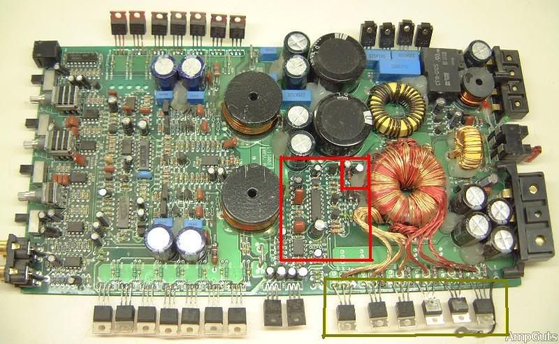
There is also a KIA393 chip in the same circuit, that I don't know how to test. This next pic shows the area of said resistors that get hot. http://i285.photobucket.com/albums/ll48 ... side12.jpg
Yellow- I have much bigger FETS there. RED- Area of problems.
That RED area drives the toroidal, and the FETS in the yellow box.
Any help would be appreciated. THANKS!
Directed 1100d reapir!
-
yesterdaysyouth
- Posts: 29
- Joined: Sun May 04, 2008 7:23 pm
the 494 is the pwm that fires the fet's, probally turns on the amp as well...
those two resistors might be tied to pins 9 and 10 which would be the outputs the way it looks.
i'm not sure what the comparator would do, probally supply the inputs of the pwm according to the rail voltage, so maybe it's always sending a high input to the pwm causing the fet's to run wide open all the time...

check to see what kinda signal you have on 9 and 10 for the output, and 1,2,15,16 for the input...
but then i'm just guessing...
those two resistors might be tied to pins 9 and 10 which would be the outputs the way it looks.
i'm not sure what the comparator would do, probally supply the inputs of the pwm according to the rail voltage, so maybe it's always sending a high input to the pwm causing the fet's to run wide open all the time...
check to see what kinda signal you have on 9 and 10 for the output, and 1,2,15,16 for the input...
but then i'm just guessing...
-
schifpine1
- Posts: 5
- Joined: Fri Apr 25, 2008 5:42 pm
Thank you for your help so far! Here are some measurements from the 494.
Pin 1-0V DC, no AC
Pin2- 5V DC, no AC
Pin15- 5V DC, no AC
Pin16-1.1 V DC, no AC
Pin9-3.1V DC, and a good looking square wave
Pin10- 250mV DC, and a very crappy looking square wave.
Following pin 10, it goes to a diode, maybe zener? and a resistor transistor setup. I lifted it from the circuit, and then its square wave looks like pin 9's. But it doesn't help anything, resistors still get hot.
Another pic to show things.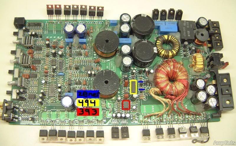
Can anyone tell me, the toroidal is used to make AC, then it is converted back into DC right? The 4 diodes that would make a bridge rectifier, are connected to the resistors that are getting hot. But they all check good.
If it helps, I can draw a schematic. THANKS
Pin 1-0V DC, no AC
Pin2- 5V DC, no AC
Pin15- 5V DC, no AC
Pin16-1.1 V DC, no AC
Pin9-3.1V DC, and a good looking square wave
Pin10- 250mV DC, and a very crappy looking square wave.
Following pin 10, it goes to a diode, maybe zener? and a resistor transistor setup. I lifted it from the circuit, and then its square wave looks like pin 9's. But it doesn't help anything, resistors still get hot.
Another pic to show things.
Can anyone tell me, the toroidal is used to make AC, then it is converted back into DC right? The 4 diodes that would make a bridge rectifier, are connected to the resistors that are getting hot. But they all check good.
If it helps, I can draw a schematic.
-
yesterdaysyouth
- Posts: 29
- Joined: Sun May 04, 2008 7:23 pm
i wouldn't think that those 4 diodes would be connected to the rails, there are rectifiers next to the power supply fets for that... maybe they supply a secondary voltage somewhere else in the amp
but there is obvisouly something wrong downstream of pin 10 though, it should be a mirror of the circuit on pin 9, have you checked the fet's themselves? you can check for shorts while they are in the board, but an open won't show unless they are all open, since they are in parallel.
but there is obvisouly something wrong downstream of pin 10 though, it should be a mirror of the circuit on pin 9, have you checked the fet's themselves? you can check for shorts while they are in the board, but an open won't show unless they are all open, since they are in parallel.

-
yesterdaysyouth
- Posts: 29
- Joined: Sun May 04, 2008 7:23 pm
i've been doing car audio a long time, and I like to think it's a much better outlet than lots of other choices, so i help out when i can. I haven't kept up with products much in the last 5 or so years so I can't help at all with equipment choices anymore  But I still remember how a power supply works... somewhat....